Pin Signal Wire color SX0B-B1105G
SX0B-B1110G
SX0B-B1114G
SX0B-B1120G
SX0B-B1105J
SX0B-B1110J
SX0B-B1505G
SX0B-B1510G
4 OSSD2 Pink
C C C
5 UNII/O1 / RESET/
C1
Red
C C C
6 UNII/O2 / EDM Yellow
C C C
7 A1 or INC1_0 White/blue
C
8 A2 or INC1_90 White/gray
C
9 B1 or INC2_0 White/violet
C
10 B2 or INC2_90 White
C
13 UNII/O3 / ERR White/black
C C C
14 UNII/O4 / WF White/brown
C C C
15 UNII/O5 /
R
ES_REQ/C2
Red/blue
C C C
16 STBY White/green
C C C
Further topics
•
"S
ystem plug", page 137
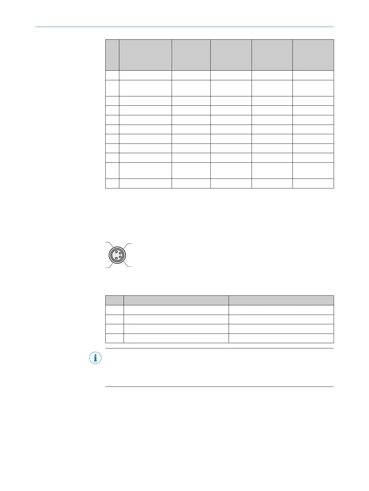
6.5 M8 × 4 configuration connection (serial interface)
Figure 56: Pin assignment on the M8 × 4 configuration connection
Table 11: Pin assignment on the M8 × 4 configuration connection
Pin Safety laser scanner PC-side RS232 DSub
1 Reserved Not assigned
2 RxD Pin 3
3 0 V DC input (power supply) Pin 5
4 TxD Pin 2
NOTE
b
Pull t
he connection cable out of the configuration connection after configuration.
b
After the device has been configured, plug the protective cap fastened to the
device back into the configuration connection.
6 ELECTRICAL INSTALLATION
72
O P E R A T I N G I N S T R U C T I O N S | S300 8010948/ZA21/2020-06-18 | SICK
Subject to change without notice

 Loading...


