7.8.1 Input delay
If the control device that you use to switch the static control inputs cannot switch to the
appr
opriate input condition within 10 ms (for example because of the switch’s bounce
times), you must configure an input delay. For the input delay, select a time in which the
control device can switch in a defined way to a corresponding input condition.
The following empirical values exist for the switchover time using various methods:
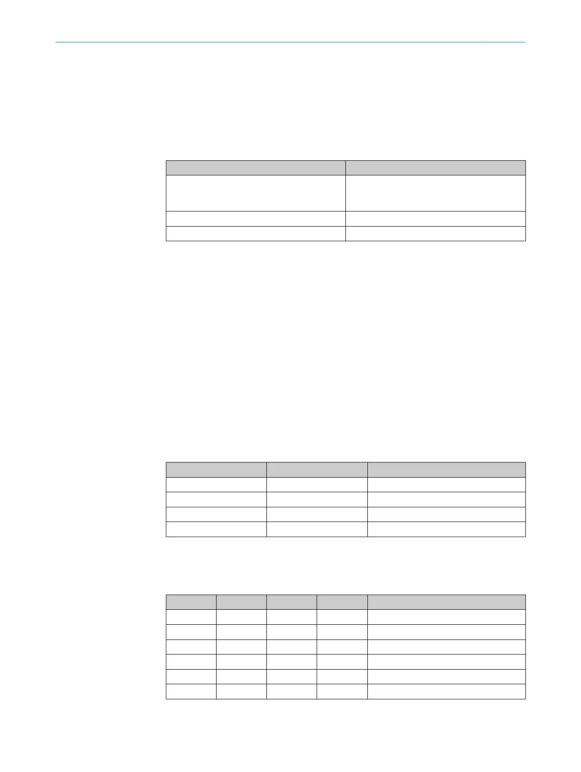
Table 17: Empirical values for the required input delay
Switching method Input delay required
Electronic switching using controller or comple‐
ment
ary electronic outputs with 0 to 10 ms
bounce time
10 ms
Contact (relay) controls 30–150 ms
Control via independent sensors 130–480 ms
Further topics
•
"T
iming for monitoring case switching", page 34
7.8.2 Sampling for the static control inputs
Overview
If y
ou are using static sampling, you can choose between complementary sampling or
1-of-n sampling depending on the control features available. Depending on this selec‐
tion, you can define the switching criteria for the monitoring cases.
Complementary evaluation
One control input comprises two connections. For correct switching, one connection
must be inverted in relation to the other.
The following table shows the levels that must be present at the connections for the
control input to define the logical input state 1 and 0 at the related control input.
Table 18: Level at the connections for the control inputs for complementary sampling
A1 A2 Logical input state
1 0 0
0 1 1
1 1 Error
0 0 Error
1-of-n sampling
W
ith 1-of-n sampling, you use the single connections of the control input pairs.
Table 19: Truth table for 1-of-n sampling with two input pairs
A1 A2 B1 B2 Result (e.g., monitoring case no.)
1 0 0 0 1
0 1 0 0 2
0 0 1 0 3
0 0 0 1 4
0 0 0 0 Error
1 1 0 0 Error
CONFIGURATION 7
8010948/ZA21/2020-06-18 | SICK O P E R A T I N G I N S T R U C T I O N S | S300
83
Subject to change without notice

 Loading...


