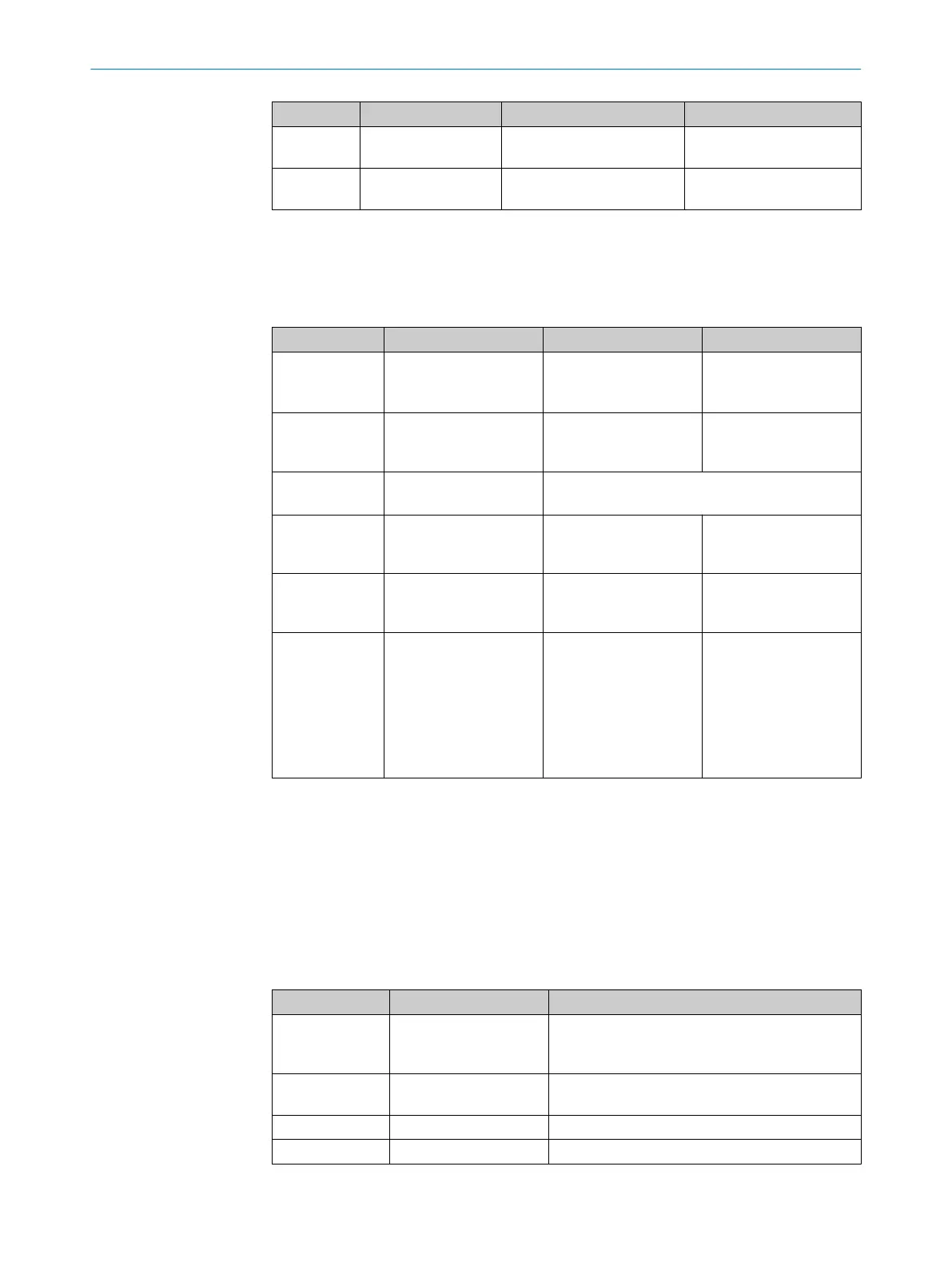
Display Output level Possible cause Rectification of the error
Í
On the universal I/
O
4)
Optics cover is dirty, opera‐
t
ion is not guaranteed
b
Cle
an the optics cover.
Ñ
On the universal I/
O
5)
Optics cover is dirty, opera‐
tion is still guaranteed
b
Cle
an the optics cover.
1)
Depending on which is configured for warning field 1 or 2.
2)
If one of the universal I/Os is configured as the output for “Reset required”.
3)
If one of the universal I/Os is configured as the output for a contamination error/warning.
4)
If one of the universal I/Os is configured as the output for a contamination error.
5)
If one of the universal I/Os is configured as the output for a contamination warning.
Table 32: Error and status indications of the LEDs in the compatibility mode
Display Output level Possible cause Rectification of the error
ÊÍ
At the OSSDs
A
t application diagnostic
output
Supply voltage missing
or too low
b
Chec
k the voltage
supply and activate,
if necessary.
Ý
At Res_Req output Reset required
b
Oper
ate the control
switch for restart or
reset.
At error/contamination
out
put
Not an error
Ð
At application diagnostic
out
put
Optics cover is dirty,
operation is not guaran‐
teed
b
Cle
an the optics
cover.
Ñ
At application diagnostic
out
put
Optics cover is dirty,
operation is still guaran‐
teed
b
Cle
an the optics
cover.
Ñ
At application diagnostic
out
put
System error
b
N
ote the error indi‐
cated on the 7-seg‐
ment display or run
diagnostics using the
CDS.
b
Switch off the
device and turn it on
again, if necessary.
Further topics
•
"St
atus indicators", page 17
•
"Pin assignment", page 65
10.3 Error and status indications on the 7segment display
This section explains the meaning of the error and status indications of the 7-segment
dis
play and how you can respond.
Table 33: Error and status indications on the 7segment display
Display Possible cause Remedy
, , , ,
, , ,
Power-up cycle - all seg‐
ment
s are activated con‐
secutively.
Not an error
Object in the protective
field
Not an error
Object in warning field 1 Not an error
Object in warning field 2 Not an error
10 TROUBLESHOOTING
114
O P E R A T I N G I N S T R U C T I O N S | S300 8010948/ZA21/2020-06-18 | SICK
Subject to change without notice

 Loading...


