Approach
1.
Mount kit 1a or 1b on the mounting surface.
2. Mount the safety laser scanner on mounting kit 1a or 1b.
NOTE
W
hen mounting the device, observe the dimensional drawings.
Further topics
•
"Dimensional dr
awings", page 135
5.2.3 Mounting using mounting kits 2 and 3
Overview
Y
ou can use mounting kits 2 and 3 (only in conjunction with mounting kit 1a or 1b) to
align the device in 2 planes. The maximum adjustment angle is ± 11° in both planes.
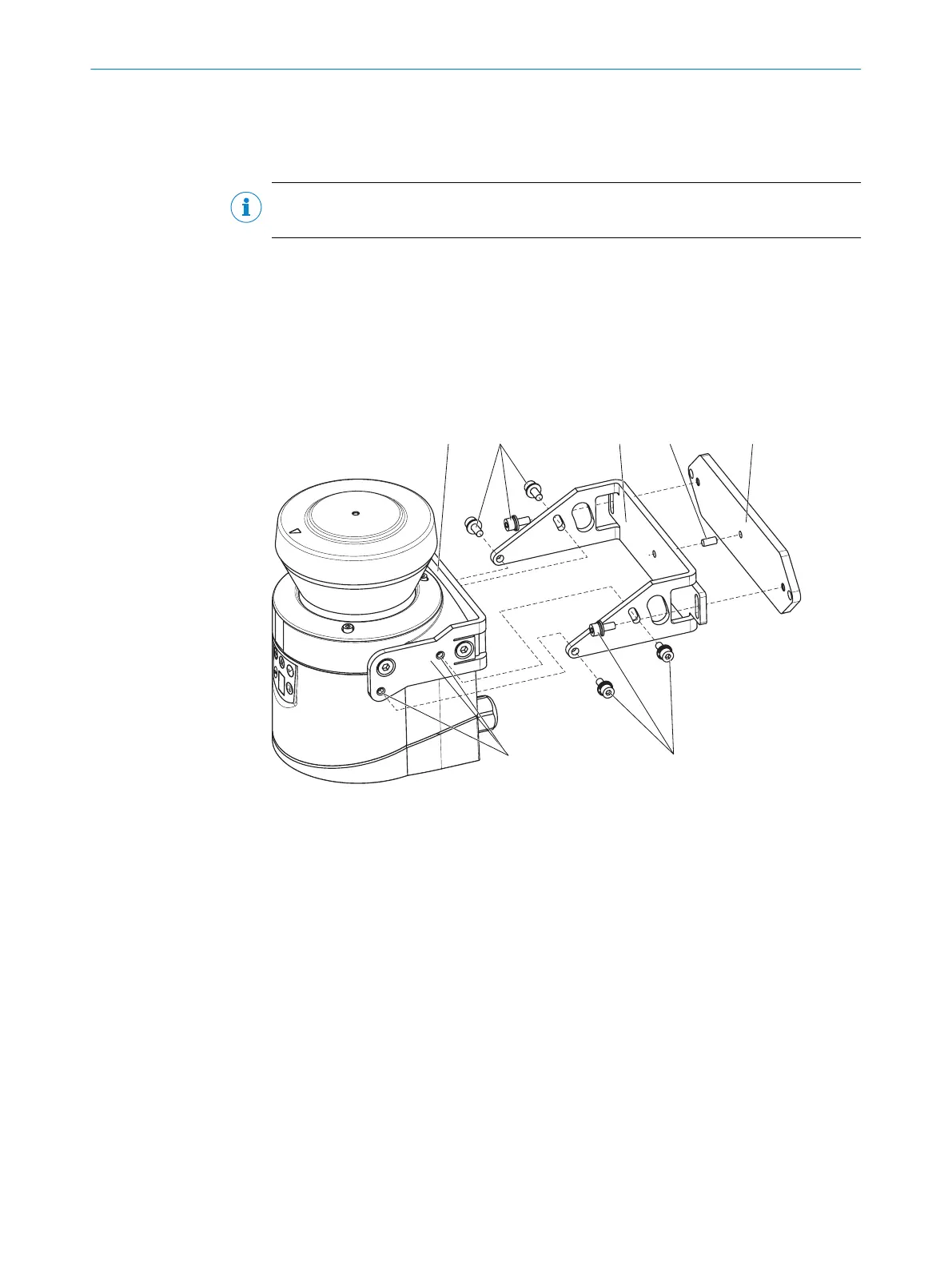
Figure 51: Mounting using mounting kit 2
1
Mounting kit 1a
2
Fixing screws
3
Mounting kit 2
4
Centring pin
5
Mounting kit 3
6
Threaded holes M4
Approach
1.
Mount kit 1a or 1b on the safety laser scanner.
2. Mount kit 3 on the mounting surface.
3. Insert the centering pin (4 mm) into the center hole of mounting kit 3.
4. Fit the mounting kit 2 onto mounting kit 3 and mount using two M4×10 fixing
screws.
5. Mount the safety laser scanner on mounting kit 2 using the threaded holes in
mounting kit 1a.
6. Adjust the safety laser scanner along the longitudinal and transversal axis then
tighten the six fixing screws on the mounting kits.
5 MOUN
TING
62
O P E R A T I N G I N S T R U C T I O N S | S300 8010948/ZA21/2020-06-18 | SICK
Subject to change without notice

 Loading...


