Monitoring case switching between an S3000 and an S300 using static and dynamic
in
puts
+24 V
0 V
FE
S3000 Professional
S300 Professional
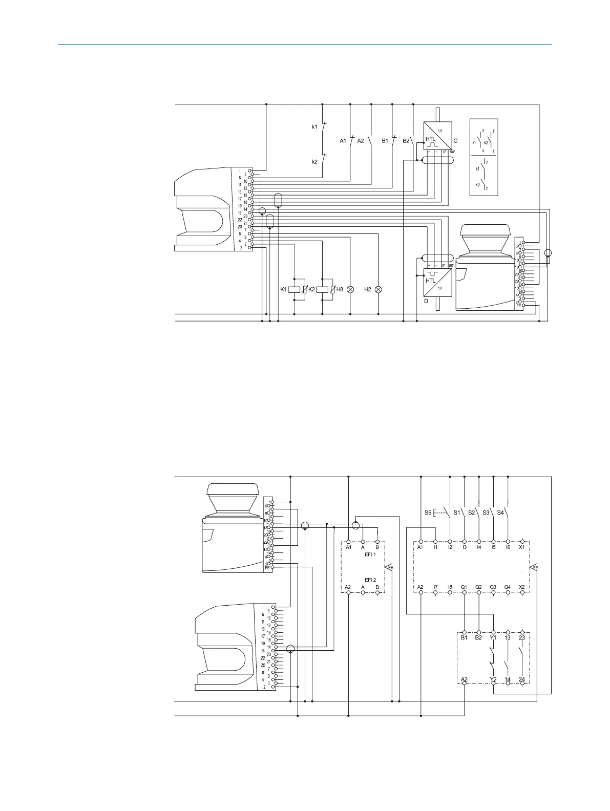
Figure 45: Connection diagram for monitoring case switching between an S3000 and an S300
usin
g static and dynamic inputs
S3000 Professional and S300 Professional in an EFI system in conjunction with relays
(contactors); Operating mode: without restart interlock, with external device monitoring;
Static monitoring case switching by the control inputs A and B of the S3000; Direction
of travel-dependent dynamic monitoring case switching by the incremental encoders C
and D of the S3000. The protective fields act on the OSSDs on the S3000.
Monitoring case switching between S3000 and S300 using a Flexi Soft safety con‐
t
roller
S300 Professional
S3000 Professional
FX3-XTIOFX3-CPU1
UE10-2FG
+24 V
FE
0 V
Figure 46: Connection diagram for monitoring case switching between S3000 and S300 usin a
F
lexi Soft safety controller
4 P
ROJECT PLANNING
56
O P E R A T I N G I N S T R U C T I O N S | S300 8010948/ZA21/2020-06-18 | SICK
Subject to change without notice

 Loading...


