6.2.1 Pin assignment
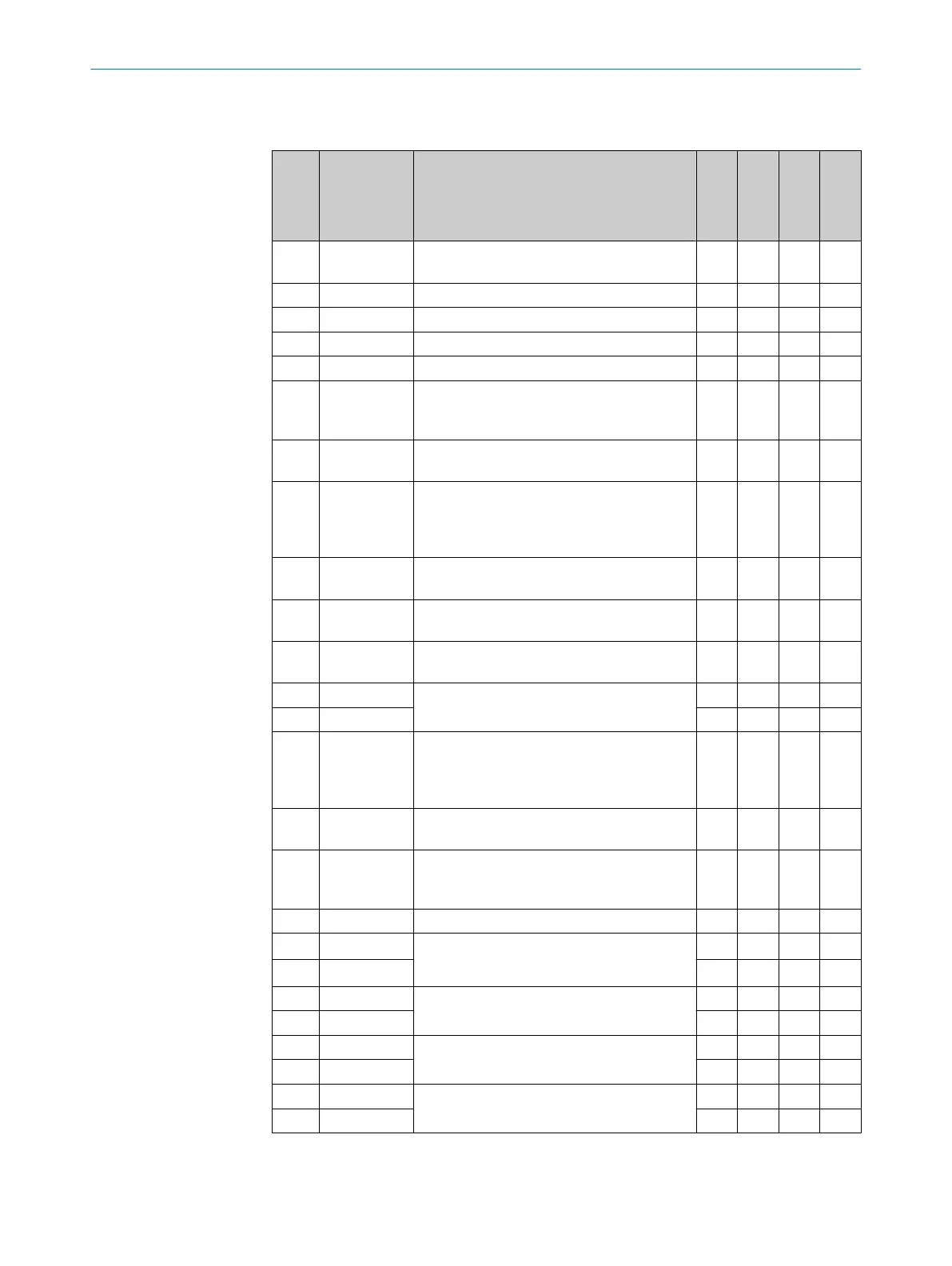
Table 7: Pin assignment on the system plug
Pin Signal Function
Standard
Advanced
Professional
Expert
FE Functional
earth
C C C C
1 24 V DC Supply voltage S300
C C C C
2 0 V DC Supply voltage S300
C C C C
3 OSSD1 Output signal switching device
C C C C
4 OSSD2 Output signal switching device
C C C C
5 UNI-I/
O1 / R
ESET/
C1
Universal I/O or input, reset, or (for the S300
Professional and Expert) static control input
C
C C C C
6 UNI-I/
O2 / EDM
Universal I/O or input, external device moni‐
toring
C C C C
7 A1 or
INC1_0
Static control input A or dynamic control
input (incremental encoder) 1
or connection for a jumper for addressing as
guest
1)
C C C C
8 A2 or
IN
C1_90
Static control input A or dynamic control
input (input for incremental encoder) 1
C C C
9 B1 or
IN
C2_0
Static control input B or dynamic control
in
put (input for incremental encoder) 2
C
2)
C C
10 B2 or
IN
C2_90
Static control input B or dynamic control
input (input for incremental encoder) 2
C
2)
C C
11 RxD–
RS422 interface for measurement data out‐
put
C C C C
12 RxD+
C C C C
13 UNII/O3 /
ER
R/WEAK
Universal I/O or application diagnostic out‐
put for error or contamination
or connection for a jumper for addressing as
guest
1)
C C C C
14 UNII/O4 / WF Universal I/O or application diagnostic out‐
put f
or Object in the warning field
C C C C
15 UNII/
O5 / R
ES_RE
Q/C2
Universal I/O or application diagnostic out‐
put for Reset required, or (for the S300 Pro‐
fessional and Expert) static control input C
C C C C
16 STBY Control input for standby mode
C C C C
17 EFI
A
Enhanced function interface = safe SICK
de
vice communication
C C C C
18 EFI
B
C C C C
19 24 V DC
Supply voltage
f
or incremental encoder 1
C C
20 GND
C C
21 24 V DC
Supply voltage
f
or incremental encoder 2
C C
22 GND
C C
23 TxD–
RS-422 interface for measurement data out‐
put
C C C C
24 TxD+
C C C C
1)
In an EFI system, a device is defined as a guest using a jumper between pin 7 and pin 13.
2)
No dynamic control input.
ELECTRICAL INSTALLATION 6
8010948/ZA21/2020-06-18 | SICK O P E R A T I N G I N S T R U C T I O N S | S300
67
Subject to change without notice

 Loading...


