NCK start-up
10.5 Parameterize axis data
CNC Part 1 (NCK, PLC, drive)
120 Commissioning Manual, 11/2006, 6FC5397-2AP10-2BA0
10.5 Parameterize axis data
See also
Configure axis data - overview (Page 285)
Axis assignment (Page 289)
Axis names (Page 291)
10.5.1 Incremental measuring system settings
Rotary measuring system
The diagrams below show the general possibilities of arranging a rotary incremental
measuring system with regard to motor and load, as well as the resulting values for the
appropriate machine data.
Figures equally apply to rotary axes, modulo axis and spindles.
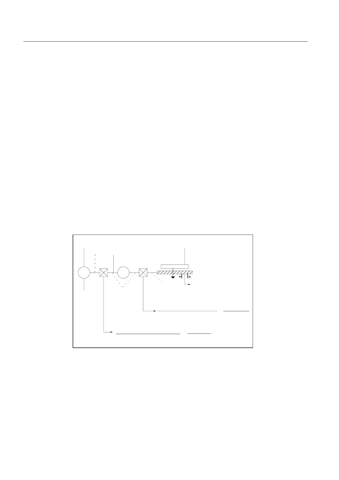
Linear axis with encoder on the machine
0
,6B527B$;
7DEOH
(1&B,6B/,1($5
(1&B5(62/
*
'5,9(B$;B5$7,2B180(5$
'5,9(B$;B5$7,2B'(120
(1&B,6B',5(&7
/($'6&5(:B3,7&+
QHQFRGHUV
0HDVXULQJ
JHDUER[
QPRWRU
/RDG
JHDUER[
QVSLQGOH
%DOOVFUHZ
'5,9(B(1&B5$7,2B180(5$
'5,9(B(1&B5$7,2B'(120
HQFRGHUUHYV
PRWRUUHYV
VSLQGOHUHYV
PRWRUUHYV
Figure 10-5 Linear axis with encoder on motor