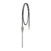
SITRANS TS300 Clamp-on:
1
3
1
4
5
6
7
8
9
10
2
PD[
a
%
%
&
&
$
$
%
%
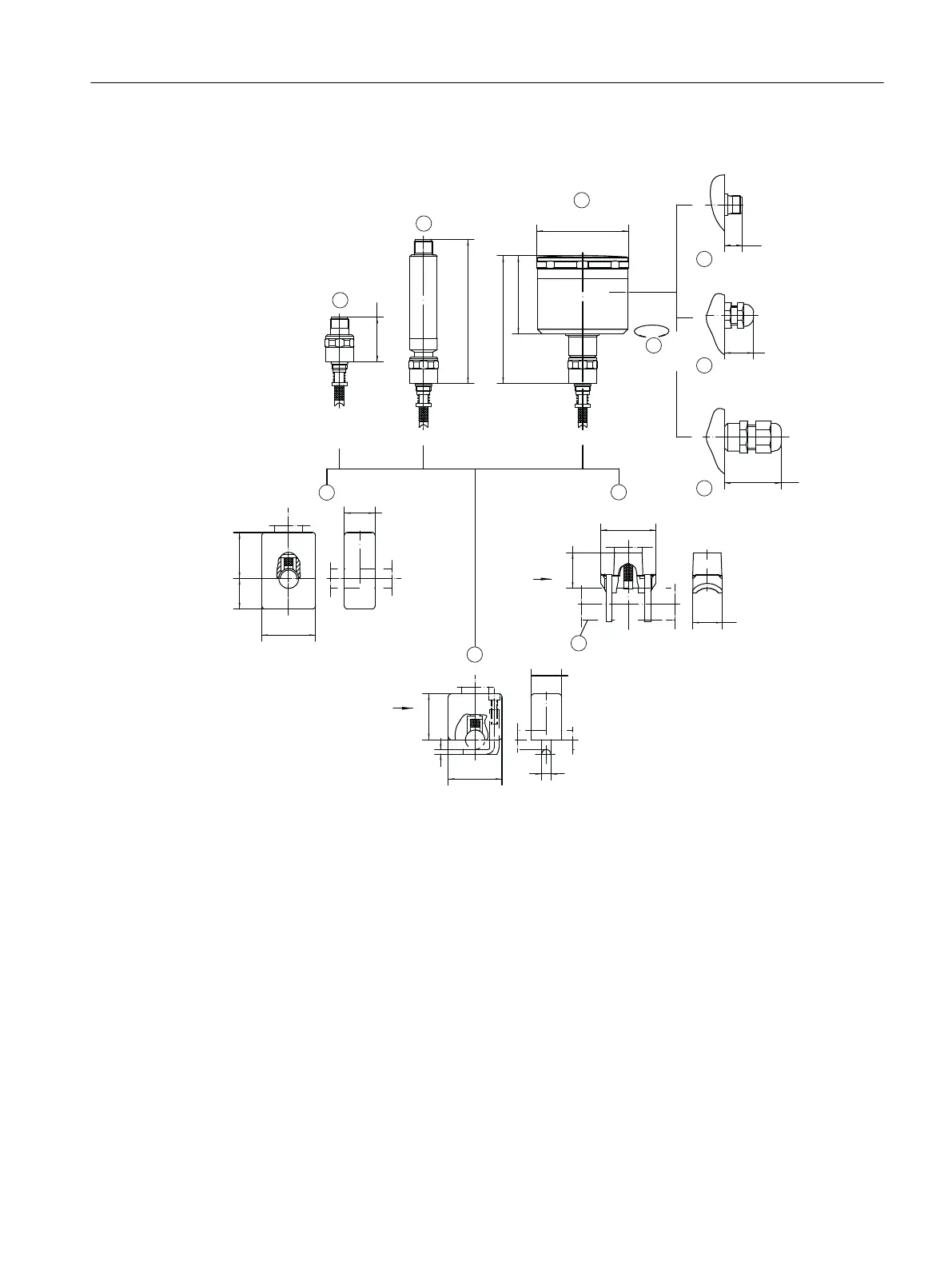
① circular connector M12 x 1 ⑥ cable connection M16 x 1,5 cable ∅4, 5-10
② transmitter with circular connector
M12 x 1
⑦ clamping shoe for pipe ≥ ∅10 - ∼∅300
③ stainless steel connection head
housing
⑧ example ∅21 (0.83)
④ electrical connection ± 170° rotata‐
ble
⑨ clamping bracket for pipe ∅4-17, 2
⑤ cable connection M12 x 1,5 cable
∅3-6, 5
⑩ clamping block for pipe ∅4-57
pipe ∅ A B C
4-17.2 (0.16 -
0.68)
20 30 35
18-38 (0.71 - 1.5) 30 40 70
38.1-57 (1.5 -
2.24)
40 50 85
Dimension drawings
12.4 SITRANS TS300
SITRANS TS100/TS200/TS300/TS500/TSinsert/TSthermowell
Operating Instructions, 08/2020, A5E47810090-AA 157