480
Sensor Basic
InstructionforMounting
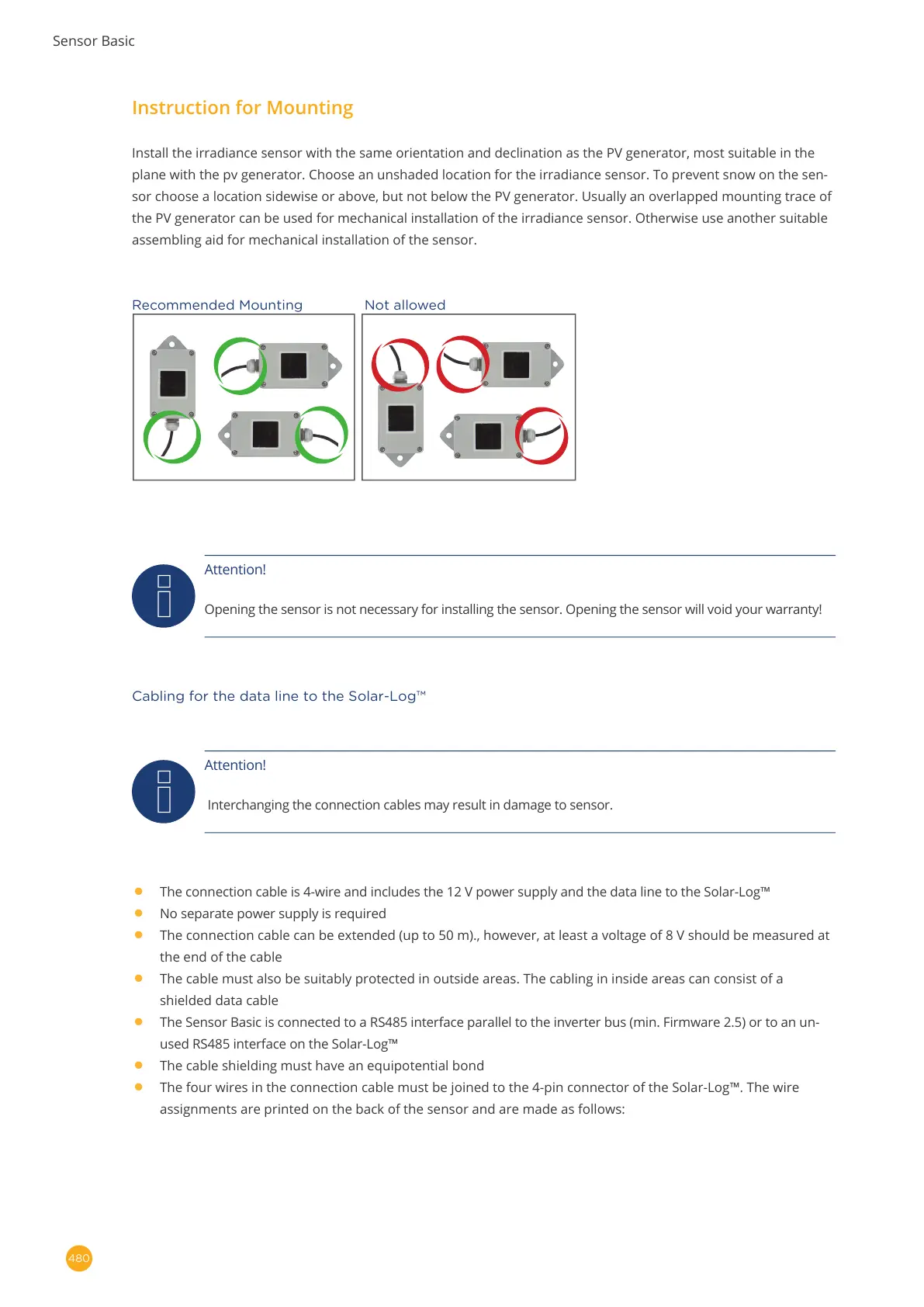
Install the irradiance sensor with the same orientation and declination as the PV generator, most suitable in the
plane with the pv generator. Choose an unshaded location for the irradiance sensor. To prevent snow on the sen-
sor choose a location sidewise or above, but not below the PV generator. Usually an overlapped mounting trace of
the PV generator can be used for mechanical installation of the irradiance sensor. Otherwise use another suitable
assembling aid for mechanical installation of the sensor.
Recommended Mounting Not allowed
Attention!
Opening the sensor is not necessary for installing the sensor. Opening the sensor will void your warranty!
Cabling for the data line to the Solar-Log™
Attention!
Interchanging the connection cables may result in damage to sensor.
•
The connection cable is 4-wire and includes the 12 V power supply and the data line to the Solar-Log™
•
No separate power supply is required
•
The connection cable can be extended (up to 50 m)., however, at least a voltage of 8 V should be measured at
the end of the cable
•
The cable must also be suitably protected in outside areas. The cabling in inside areas can consist of a
shielded data cable
•
The Sensor Basic is connected to a RS485 interface parallel to the inverter bus (min. Firmware 2.5) or to an un-
used RS485 interface on the Solar-Log™
•
The cable shielding must have an equipotential bond
•
The four wires in the connection cable must be joined to the 4-pin connector of the Solar-Log™. The wire
assignments are printed on the back of the sensor and are made as follows: