EasyManua.ls Logo

Staubli CS8C User Manual

Staubli CS8C
248 pages
To Next Page IconTo Next Page
To Previous Page IconTo Previous Page
Page #146 background imageLoading...
Page #146 background image
© Stäubli 2009 – D28070504A CS8C146 / 248
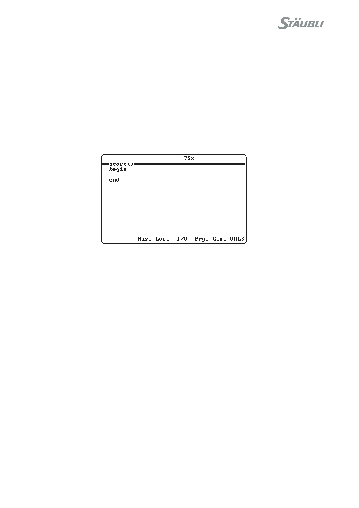
When adding or modifying an instruction, a list of menus makes it easier to enter. (see figure 6.17)
His. enables you to select an instruction in the list of the last 20 instructions entered.
Loc. enables you to search for or create a local variable or a parameter.
I/O enables you to select an Input/Output.
Prg. enables you to select or create a new program.
Glo. enables you to select or create a global variable.
VAL3 enables you to select an instruction in the list of VAL3 instructions.
It is possible to insert a breaking point in an instruction (see paragraph 6.10.3).
To exit, press the Esc key.
Figure 6.17

Table of Contents

Question and Answer IconNeed help?

Do you have a question about the Staubli CS8C and is the answer not in the manual?

Staubli CS8C Specifications

General IconGeneral
Number of AxesUp to 6
Programming LanguageVAL3
Protection ClassIP 54
Humidity5 to 95% non-condensing
Compatible RobotsStaubli robots
Communication InterfacesEthernet, Serial, Fieldbus
SafetySafety PLC integration
Operating Temperature0 to 45°C
Storage Temperature-20°C to 60°C

Summary

Chapter 2 Description of the Controller

2.2. LOCATION AND DESCRIPTION OF THE MAIN COMPONENTS

Describes the CS8C controller, including processor, power amplifiers, and safety boards.

Chapter 3 Safety

3.1. REMINDER CONCERNING THE SAFETY STANDARDS

Outlines safety standards applicable to robots and robot cells, emphasizing compliance and training.

3.2. SAFETY DIRECTIVES CONCERNING TO THE WORK ENVIRONMENT

Covers safety considerations for the robot cell environment and work area.

3.3. SAFETY DIRECTIVES CONCERNING TO STAFF PROTECTION

Addresses mechanical and electrical dangers, and safety measures for personnel.

Chapter 4 Installation

4.2. ON-SITE PREPARATION

Covers electrical and pneumatic network requirements, work environment, and controller mounting.

4.6. CONNECTIONS

Covers connections to the mains power supply, arm, and signals, including cable management.

Chapter 5 Integration

5.1. EMERGENCY AND SAFETY STOP CHANNELS

Describes the composition and connection of emergency and safety stop channels.

5.7. PROGRAMMABLE LOGIC CONTROLLER (PLC OPTION)

Details PLC option installation, operation, programming, and debugging.

Chapter 6 Operation

6.1. POWERING UP THE CONTROLLER

Provides instructions on how to safely power up the controller.

6.2. PRESENTATION OF THE MCP

Details the general presentation, control keys, and display of the Manual Control Pendant (MCP).

6.3. ARM POWER-UP

Explains the procedure for powering up the robot arm safely.

6.4. EMERGENCY STOP

Describes the emergency stop function and the procedure to restore power.

6.5. CALIBRATION, ADJUSTMENT, RECOVERY

Covers definitions, recovery procedures, and adjustment procedures for arm calibration.

6.7. JOG INTERFACE

Explains the jog interface for manual control, movement modes, and point teaching.

Chapter 8 MAINTENANCE

8.4. SAFETY

Reiterates safety precautions, including disconnecting power and handling components.