CS8C © Stäubli 2009 – D28070504A
193 / 248
Chapter 8 - Maintenance
8.6.7.4. ADVANCED INFORMATION
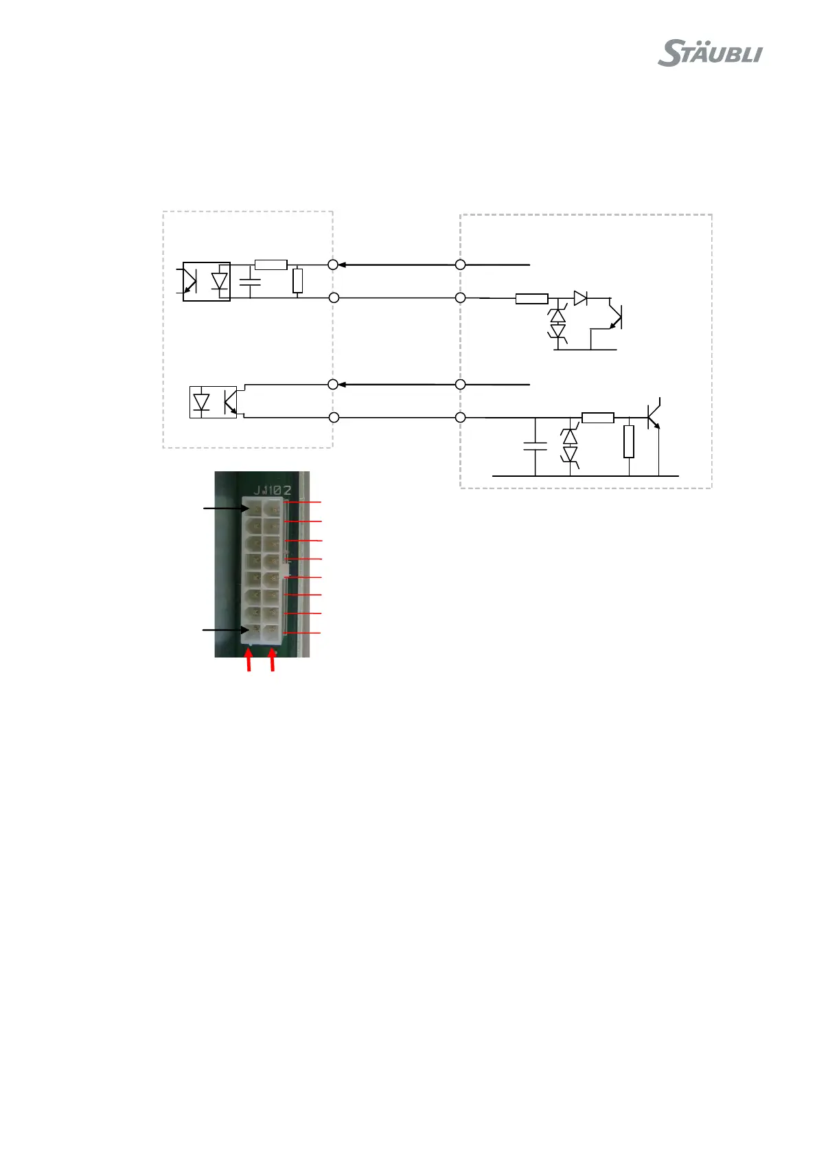
Input and output are 24 VDC signals.
BRK_REL_EN is active (status in control panel = ON) when BRK_REL_EN signal is set to 0V.
In that case, BRK_ON feedback signal goes to 24 VDC (RSI input = ON, status in control panel = ON).
Figure 8.31
RSI
ARPS
BRK_REL_EN+
BRK_REL_EN-
J1102-7
J1102-15
J104-4
J104-9
24V
BRK_ON+J1102-8 J104-5
BRK_ON-J1102-16 J104-10
24V
GND
GND
BRK-ON
Pin 8
ALIM-OK
24V1
24V1
24V2
13V
0 VDC+
SECTEUR-OK
BRK-REL-EN
Pin 1
Output from ARPS to
RSI
Output from RSI to ARPS