CS8C © Stäubli 2009 – D28070504A
215 / 248
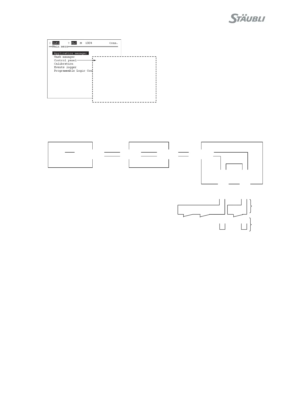
Chapter 8 - Maintenance
Figure 8.50
The maximum angular range is defined in the robot' product characteristics.
• If arm is inside its predefined range, check wiring inside the arm.
Figure 8.51
• Check wiring from RSI to the arm base (mainly the interconnection cable).
• If wiring is OK, change RSI board.
- Controller status
...
- Joint position
J1: xx J2: xx J3: xx
...
J4: xx J5: xx J6: xx
+WSL7-
00
7J
-WSL4-00
7J
4-6M1021J
3-6M1021J
4-6M002
1
J
3-6M0021J
J701
-16 LSW2-
J701-15 LSW2+
J701-14 LSW1-
J701-13 LSW1+
21-101J
+01WSL
5-101J-01WSL
sufV42
ISR
3WSL 2WS
L
1WSL
11
444
1
,0
6
X
T
,
0
9
XT
061XR
04XT
CIBRB