© Stäubli 2009 – D28070504A CS8C224 / 248
8.8.4.17. CASE 17
This E-Stop is coming from the cell and is connected to RSI J109.
• Check wiring from this E-Stop to J109 14-33 and 15-34.
Note:
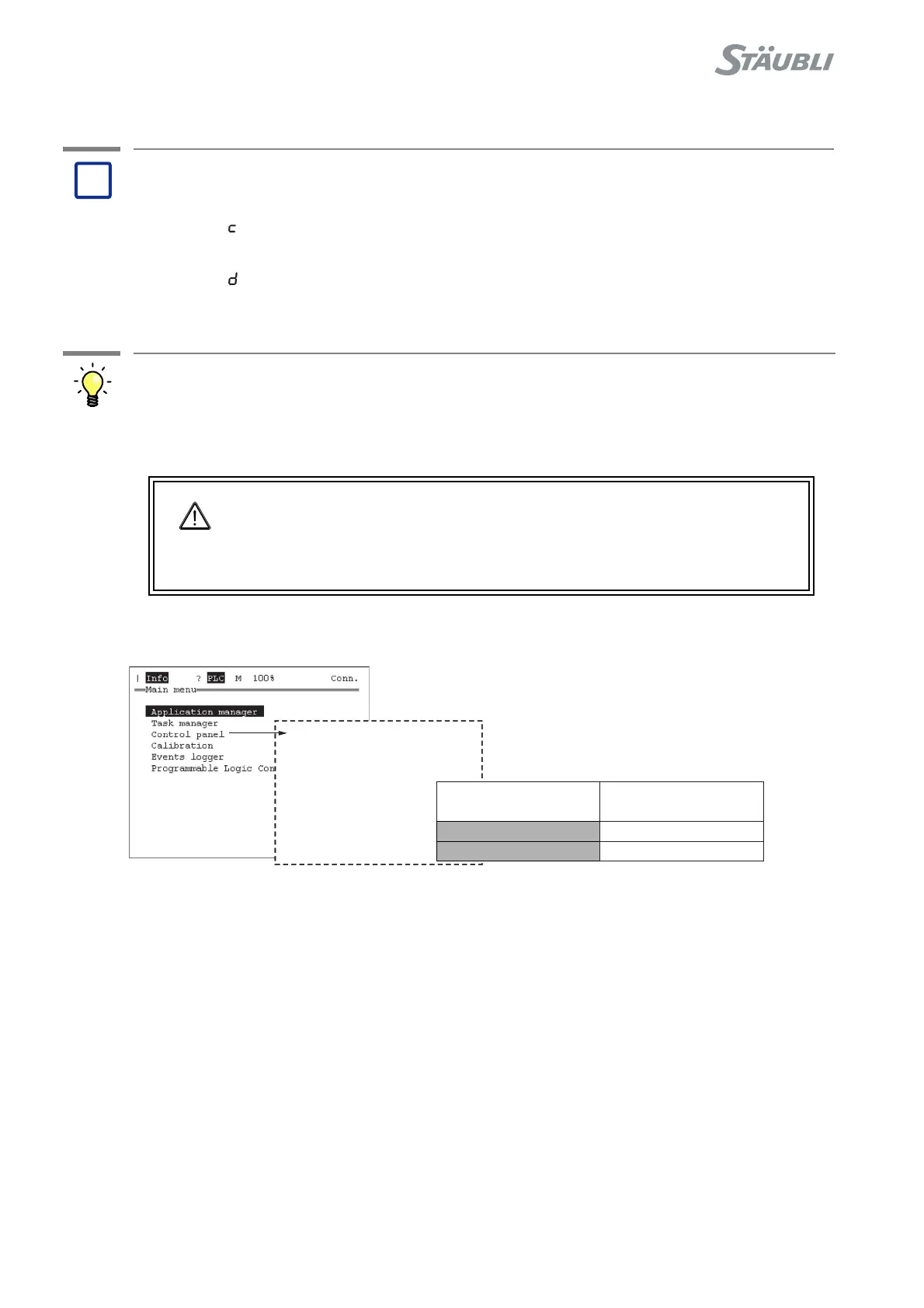
Status of manual brake release switch can be obtained from MCP Control Panel:
Figure 8.61
Problem:
(c) User emergency stop B1 activated: Contact UESB1, J109, 14-
33
(d) User emergency stop B2 activated: Contact UESB2, J109, 15-
34
Solution:
DANGER:
If only one E-Stop contact is operating, the robot will be stopped but unsafely.
It is mandatory to repair the E-Stop line to get both contacts operating: No
error code on RSI and same status on both E-Stop lines on MCP Control
Panel.
?
- Controller status
- I/O
-SystemIO
- Inputs
...
24 UESB1=
25 UESB2=
E-Stop activated
ON
ON
E-Stop released
OFF
OFF