OnAir 2000M2 Digital Mixing Console
Date printed: 12.11.03 SW V 4.0 HW Modules 15-15
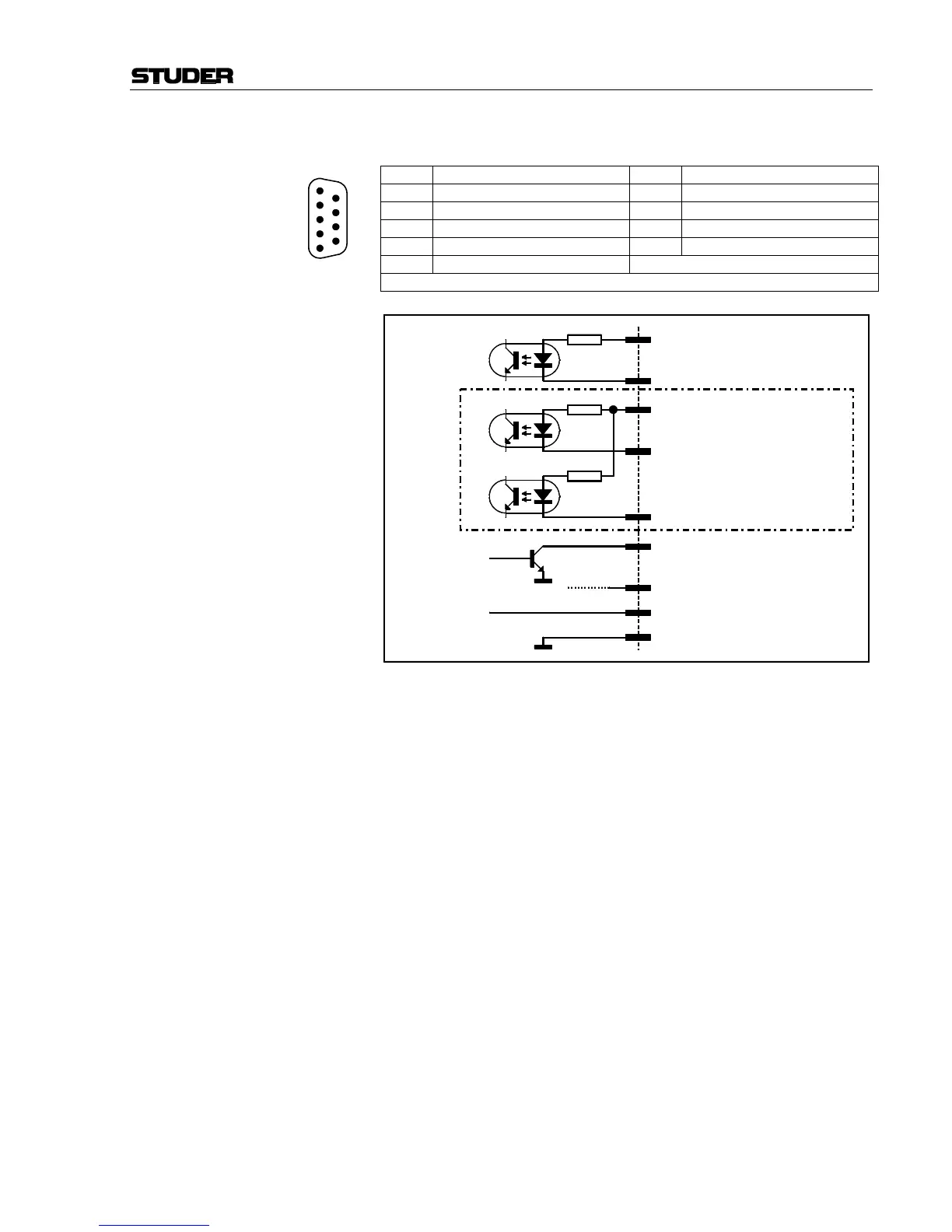
EXT PFL CTRL (D-type, 9 pin, male):
Pin Signal Pin Signal
1 +5 V SUPPLY 6 External PFL IN +
2 External PFL IN – 7 n.c. / External TB to CR – (note 1)
3 External PFL OUT 8 Spare OUT
4 External TB COMMON + (note 1) 9 n.c. / Ext. TB to Studio – (note 1)
5 GND
Note 1: Available on 1.942.180.xx and 1.942.181.xx only.
Notes: “External PFL IN +” and/or “External TB COMMON” can be connected
either to “+5 V SUPPLY” or to an external power supply (max. +15 V
DC
).
A pushbutton or an active-low control signal from a radio automation sys-
tem is connected between the „ – ” control inputs and “GND”. The inputs
are opto-coupler inputs with internal 1 kΩ current limiting resistors.
The “External PFL OUT” output is an open-collector output; small loads,
such as an LED, an opto-couplers, or a relay can be driven directly. The
current must not exceed 100 mA.
The “+5 V” supply current for an opto-coupler or a relay must not exceed
50 mA.
1
2
3
4
5
6
7
8
9
1 kΩ
6 External PFL IN +
1 +5 V SUPPLY
max. 50 mA
+5 V
max. 100 mA
5 GND
2 External PFL IN –
3 External PFL OUT
8 Spare OUT
1 kΩ
4 External TB COMMON +
7 External TB to CR –
1 kΩ
9 External TB to studio –
1.942.180 and
1.942.181 only