OnAir 2000M2 Digital Mixing Console
15-16 HW Modules SW V 4.0 Date printed: 12.11.03
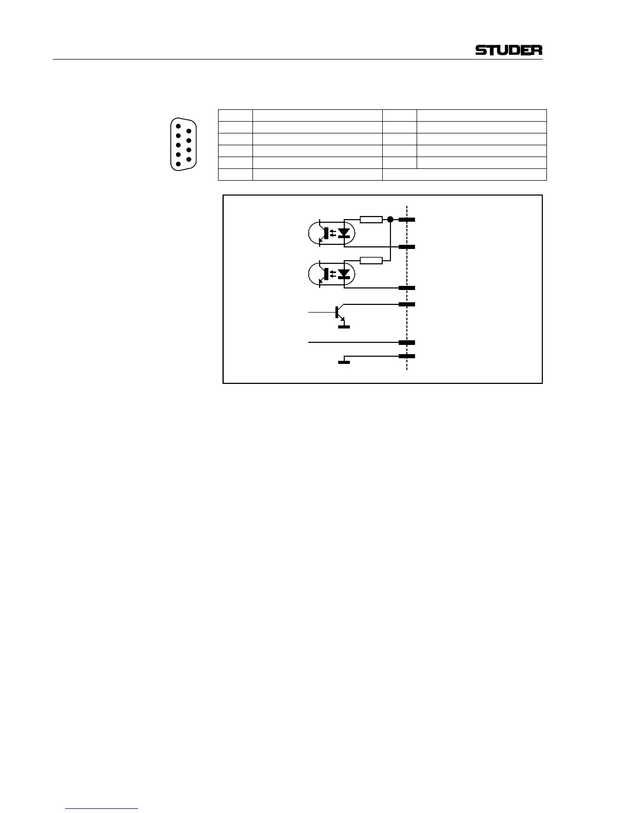
SIGN. (D-type, 9 pin, male):
Pin Signal Pin Signal
1 +5 V SUPPLY 6 COMMON
2 ON AIR IN – 7 Spare IN – or Ext. CR DIM IN – *
3 CR MIC OUT 8 STUDIO MIC OUT
4 PGM OUT 9 Spare OUT
5 GND
* depending on Customer Code setting
The “ON AIR IN – ” signal turns on the “ON AIR” lamp on the console's
monitoring section.
The “CR MIC OUT” output is active if any microphone in the control
room is on (i.e. fader open, ON pushbutton active, signal routed to the
PROGRAM or RECORD bus).
The “STUDIO MIC OUT” output is active if any microphone in the studio
is on (i.e. fader open, ON pushbutton active, signal routed to the
PROGRAM or RECORD bus).
The “PGM OUT” output is active if any input channel is on (i.e. fader
open, ON pushbutton active, signal routed to the PROGRAM or RECORD
bus).
If set with the Customer Code (refer to chapter 12.2.12), an external con-
trol signal at the “Ext. CR DIM IN – ” input reduces (dims) the level of the
CR monitor speakers by 20 dB.
Notes: “COMMON” can be connected either to “+5 V SUPPLY” or to an external
power supply (max. +15 V
DC
). Active-low control signals are connected
between the control inputs and “GND”. The inputs are opto-coupler inputs
with internal 1 kΩ current limiting resistors.
The outputs are open-collectors; small loads, such as LEDs, opto-couplers,
or relays can be driven directly. The current must not exceed 100 mA per
output.
The “+5 V” supply current must not exceed 50 mA.
1
2
3
4
5
6
7
8
9
1 kΩ
6 COMMON
1 +5 V SUPPLY
max. 50 mA
+5 V
max. 100 mA
5 GND
2 ON AIR IN –
3, 4, 8, 9 OUTPUTS
7 Spare IN – / Ext. CR DIM IN – *
1 kΩ
* depending on Customer Code setting