OnAir 2000M2 Digital Mixing Console
Date printed: 12.11.03 SW V 4.0 HW Modules 15-17
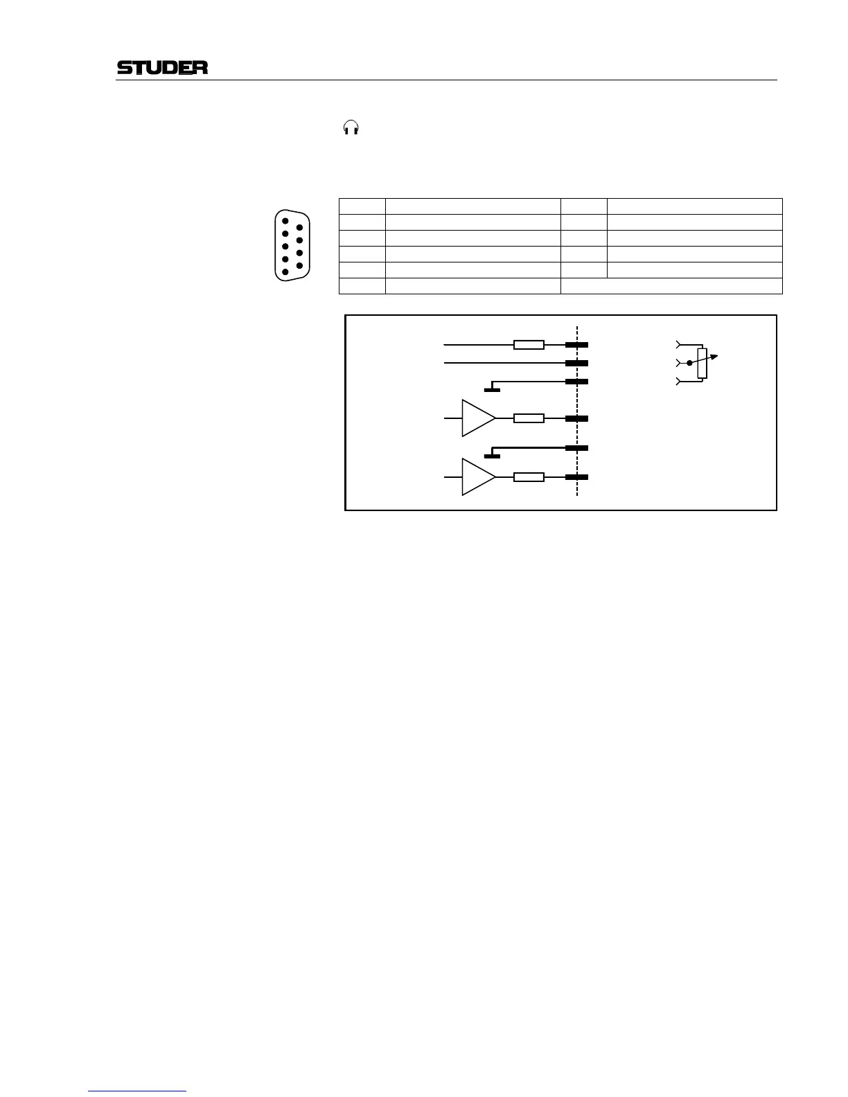
CTRL (D-type, 9 pin, male):
This connector provides all the signals required for a guest headphone.
The “Phones OUT” signal is the same as the one on the GUEST jack
socket on the same module.
Pin Signal Pin Signal
1 Phones OUT left 6 Phones OUT right
2 GND 7 n.c.
3 GND 8 n.c.
4 Potentiometer wiper 9 n.c.
5 +5 V SUPPLY
Notes: A linear 10 kΩ volume control potentiometer can be connected between
“+5 V SUPPLY” and “GND”. The volume is maximum if the wiper volt-
age is at +5 V.
The signal on pins 1 and 6 is the same as the one on the GUEST head-
phones jack socket.
1
2
3
4
5
6
7
8
9
120 Ω
2 GND
+5 V
1 Phones OUT left
Pot. wiper
6 Phones OUT right
100 Ω
120 Ω
5 +5 V SUPPLY
3 GND
4 Pot. wiper 10 kΩ, lin.
↑ level max.
↓ level min.