Overview
22
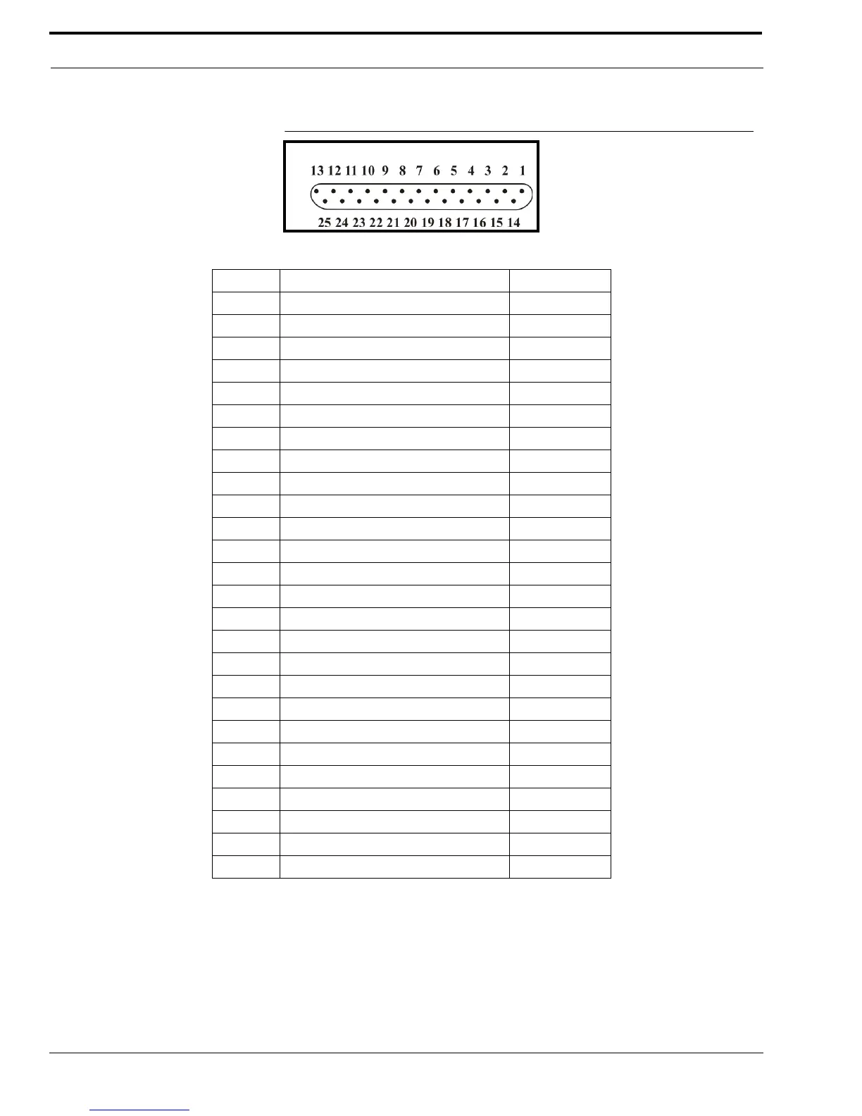
FIGURE 6. DB25 Connector Pinout Configuration
TABLE 4. DB25 Connector Pinout Connections
Pin # Signal Cable color
1 PTT Relay N.C. Brown
2 PTT Relay Common Red
3 MON Relay N.O. Orange
4 R1 Relay N.C. Pink
5 R1 Relay Common Yellow
6 R2 Relay N.O. Green
7 Ground Lt. Green
8 Digital 0/X-Mute Blue
9 Digital 2 Violet
10 Digital 4 Gray
11 CTCSS White
12 Radio RX- in / 4-Wire RX Black
13 Radio TX- out / 4-Wire TX or 2-Wire Brown/White
14 PTT Relay N.O. Red/White
15 MON Relay N.C. Red/Black
16 MON Relay Common Orange/White
17 R1 Relay N.O. Orange/Black
18 R2 Relay N.C. Pink/Black
19 R2 Relay Common Yellow/Black
20 Digital 6/COR Green/White
21 Digital 1/Supervisory Green/Black
22 Digital 3 Blue/White
23 Digital 5/Local PTT Violet/White
24 Radio RX+ input / 4-Wire RX Gray/Black
25 Radio TX+ out / 4-Wire TX or 2-Wire Black/White
Shield Ground