Installation and Level Settings
32
Tone and Console Operation
Tone and Console operation require jumpers set to specific locations. For more information, see “Jumper Locations” on
page 131.
2-/4-Wire Jumper Settings
The RX termination J14 (line 1) and J24 (line 2) should be placed in jumper position A on 4-wire systems for a single unit at
the end of a line. If multiple units are connected in parallel, only one (1) unit should have the RX termination jumper in the A
position. The RX termination jumper should be in the null position on the rest of the units.
For 2-wire operation:
• PCB 750743 or PCB 750630 revision C and higher - Set J14 or J24 to the NULL position.
TX Side Settings
PCB 750743 or PCB 750630 revision C and higher
Two (2) jumpers on the transmit pair allow a degree of control over the output impedance. The jumper positions for each line,
depending on how many consoles are placed in parallel, are shown in Table 10.
NOTE: PCB 750630 revision A does not have these jumpers.
Local PTT I/O
The Local PTT I/O is used to generate TX Ethernet traffic on a system in local mode as opposed to the 2175Hz detection on
a system in tone mode. The input is at DIG5; pin 23 of the DB25 connector. The TX condition is caused by an active low.
Cross Mute I/O
Cross Mute I/O information to local consoles is provided at DIG0, pin 8 of the DB25 connector.
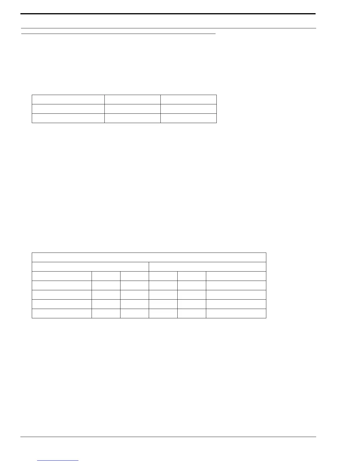
TABLE 9. 2- and 4-Wire Jumper Settings
2-Wire / 4-Wire Selection: Line 1 Line 2
2-Wire A position J33 and J34 J5 and J6
4-Wire B position J33 and J34 J5 and J6
TABLE 10. PCB 750743 or PCB 750630 Revision C and Higher
Jumper Position
Line 1 Line 2
Consoles in Parallel: J17 J22 J10 J15 Output Impedance
1 BBBB600 ohms
2 A B A B 1200 ohms
3 B A B A 1800 ohms
4 A A A A 2400 ohms