21
Back Panel
Serial Connector
The Serial connector (DB9) is used for either of the following:
• Programming an initial IP Address into the IP-223 unit, if the IP Address cannot be programmed through the
Ethernet port on the installed system.
NOTE: The jumper setting must be RS-232, to communicate with HyperTerminal.
• Providing serial communication to various radios. Both radio 1 and radio 2 are supported on this connector, with
the appropriate splitter cable.
NOTE: You must adjust the position of the jumper, on J35 when using line 1, or on J26 when using line 2, according to
the serial connection type for the radio interface shown below. For more information, see “Jumper Positions” on
page 27.
Radio 1 and Radio 2 Connectors
Two (2) DB25 connectors are provided for connection to various audio devices. The pinouts shown in Table 4 are used when
custom cables need to be fabricated.
Power Connection
The IP-223 requires +12 to +16VDC, ~700mA of clean power. A 3-pin screw terminal receptacle is provided on the right rear
of the unit. Pin 1 is the positive terminal, pin 2 is the ground terminal, and pin 3 is the earth ground terminal.
As with all communication equipment, earth ground should be used. Earth ground is a low impedance path to the earth for the
purpose of discharging lightening, static, and radiated energy.
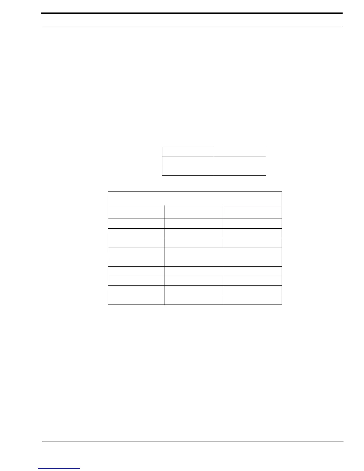
TABLE 2. Jumper Position
Jumper position Connection type
A RS-232
BTTL
TABLE 3. DB9 Pinout
SERIAL DB9 PINOUT
SIGNAL LINE # DB9 PIN #
TX 232 1 2
RX 232 1 3
TX TTL 1 9
RX TTL 1 1
Ground both 5
TX 232 2 8
RX 232 2 7
TX TTL 2 4
RX TTL 2 6