27
CHAPTER 3
Installation and Level Settings
Local Radio Connections
NOTE: Connections to radios differ from connections for remote operation; therefore connections are discussed
separately.
Jumper Positions
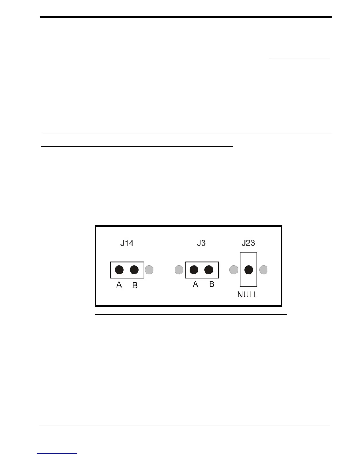
An example of the jumper positions are shown in Figure 7. In the figure, jumper 14 (J14) is shown in position A, jumper 3
(J3) is shown in position B, and jumper 23 (J23) has been placed on the center pin indicating the jumper is in the NULL
position.
FIGURE 7. Jumper Positions