EasyManua.ls Logo

Tescom TC-3000C - I;Q Modulation Calibration; [Figure 6] I;Q Modulation Calibration Test

Default Icon
255 pages
Print Icon
To Next Page IconTo Next Page
To Previous Page IconTo Previous Page
Loading...
2.6 Cleaning, Storage and Shipment
88
4.2.2 I/Q modulation calibration
Equipment: Spectrum Analyzer, HP8561E
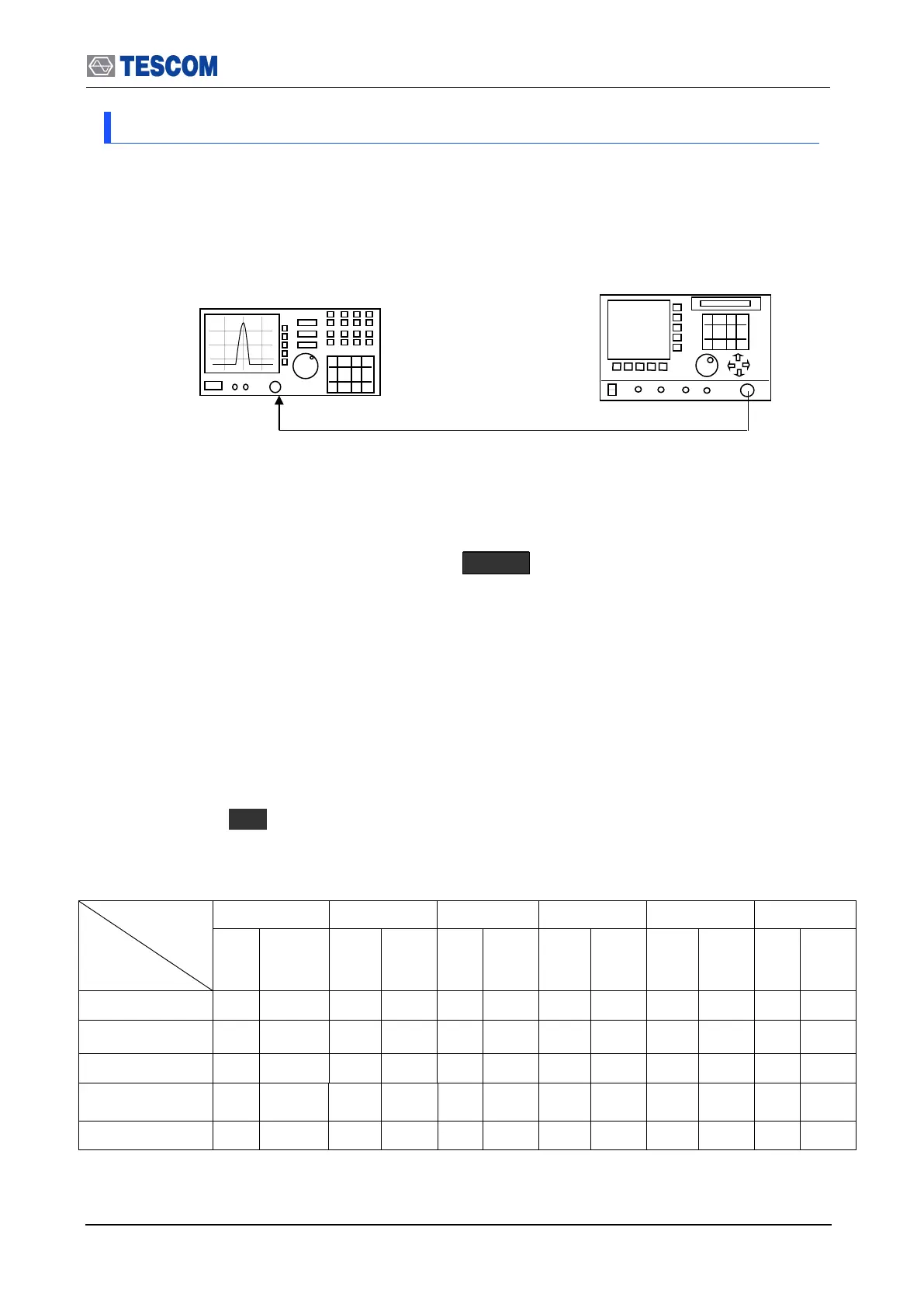
1. Test Setup: Connect equipment as shown in the figure below
[Figure 6] I/Q modulation calibration test
2. Set controls of TC-3000C as follows:
Set TC-3000C to “Signal Generator” mode. ( MENU Select “SigGen”)
- Power: 0dBm
- Bit Patten: 0
- FM Deviation:150 kHz
3. Set controls of Spectrum Analyzer as follows:
Span: 1 MHz
RBW: 10 kHz
VBW 210 kHz
4. Set TC-3000C output frequency according to the table below. At each setting,
press “Start” ( F1 ) to begin the test.
5. Record the level in the table for each setting. The limits for this frequency are
given in the table.
Fc
Spectrum
Marker
2400 MHz
2420 MHz
2440 MHz
2460 MHz
2480 MHz
2500 MHz
Spec.
Spec.
Spec.
Spec.
Spec.
Spec.
Fc-300kHz
<=-
31dBm
<=-
31dBm
<=-
31dBm
<=-
31dBm
<=-
31dBm
<=-
31dBm
Fc-150kHzt
<=-
31dBm
<=-
31dBm
<=-
31dBm
<=-
31dBm
<=-
31dBm
<=-
31dBm
Fc
1>=, >=-1
1>=,
>=-1
1>=,
>=-1
1>=,
>=-1
1>=,
>=-1
1>=,
>=-1
Fc+150kHz
<=-
31dBm
<=-
31dBm
<=-
31dBm
<=-
31dBm
<=-
31dBm
<=-
31dBm
Fc+300kHz
<=-
31dBm
<=-
31dBm
<=-
31dBm
<=-
31dBm
<=-
31dBm
<=-
31dBm
TC-3000C
2450 MHz
INPUT 50
HP 8561E

Table of Contents

Related product manuals