HYDROSTATIC POWER TRAIN
4181383 First Edition 5-33
5
Installation Notes
• Install the 4WD valve by reversing the order of
removal.
• Ensure new O-rings are in place before installing
hoses on fittings.
• Pressure filter traction system. (See “Portable In-Line
Filter” on page 5-2.)
• Fill the hydraulic tank. (Refer to “Safety, Operation,
and Maintenance Manual” for the correct oil
specifications.)
• Start engine. Check for leaks and repair as
necessary.
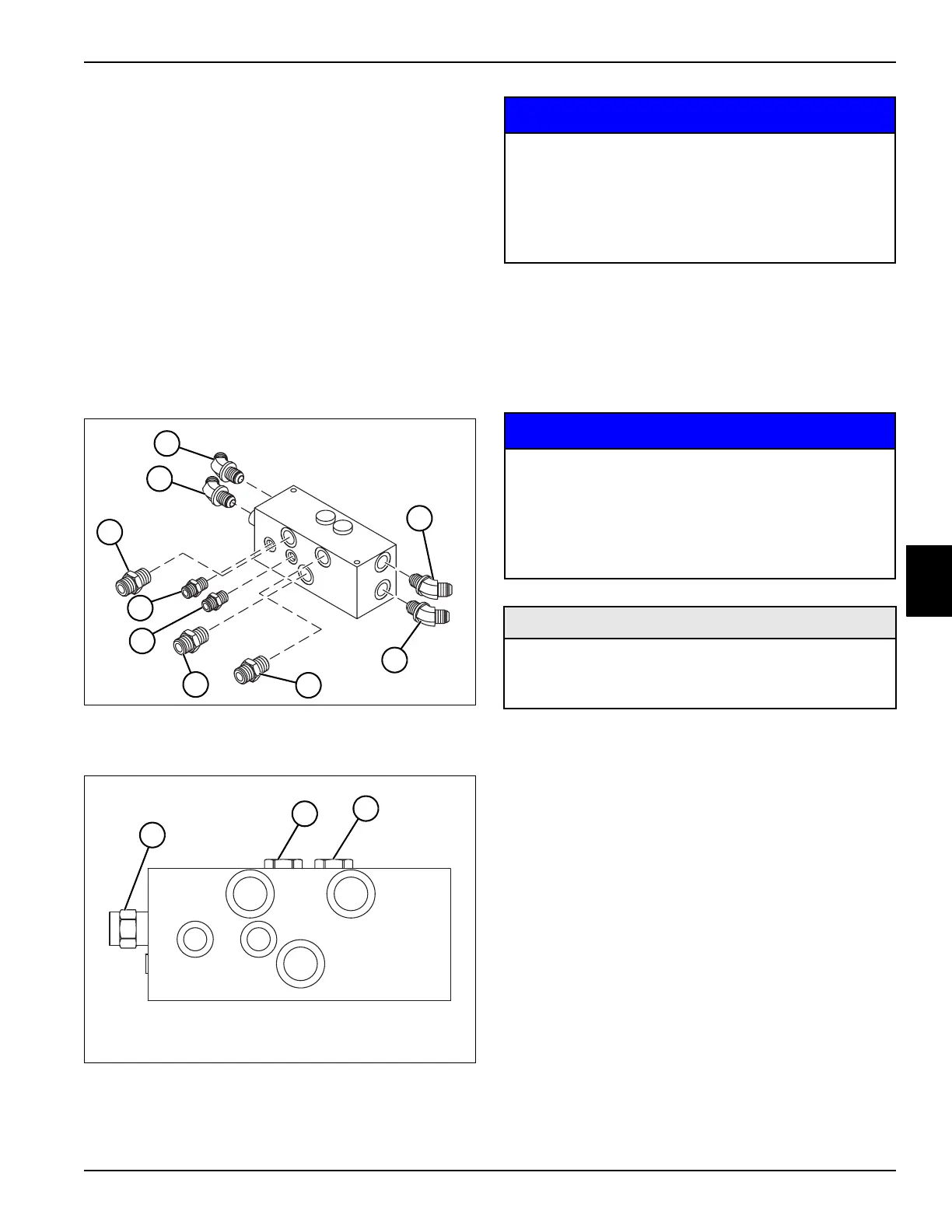
Disassembly, Inspection, and Assembly
See Figures 5-32 and 5-33.
Figure 5-32
1. Remove fittings (1—9) from the 4WD valve.
Figure 5-33
2. Remove hot oil shuttle (4).
3. Remove check valves (5 and 6).
NOTICE
4. Clean all parts using clean solvent, and dry using
compressed air.
5. Inspect all parts for wear or damage. Replace parts
as needed.
Assembly Notes
NOTICE
• Assemble the 4WD valve by reversing the order of
disassembly.
• Lubricate all O-rings prior to assembly.
TN1515
2
3
4
1
8
7
9
6
5
TN1517
4
5
6
It is important that all component parts are
absolutely clean, as contamination can result in
serious damage and/or improper operation.
Never use shop towels or rags to dry parts after
cleaning, as lint may clog passages. Dry parts
using compressed air.
It is important that all component parts are
absolutely clean, as contamination can result in
serious damage and/or improper operation.
Never use shop towels or rags to dry parts after
cleaning, as lint may clog passages. Dry parts
using compressed air.
Required Materials
Seal Kit, Check Valve (Jacobsen P/N 5003579)
Seal Kit, Pilot Operated Internal Vent Valve
(Jacobsen P/N 5003579)
 Loading...


