HYDRAULICS
4181383 First Edition 6-27
6
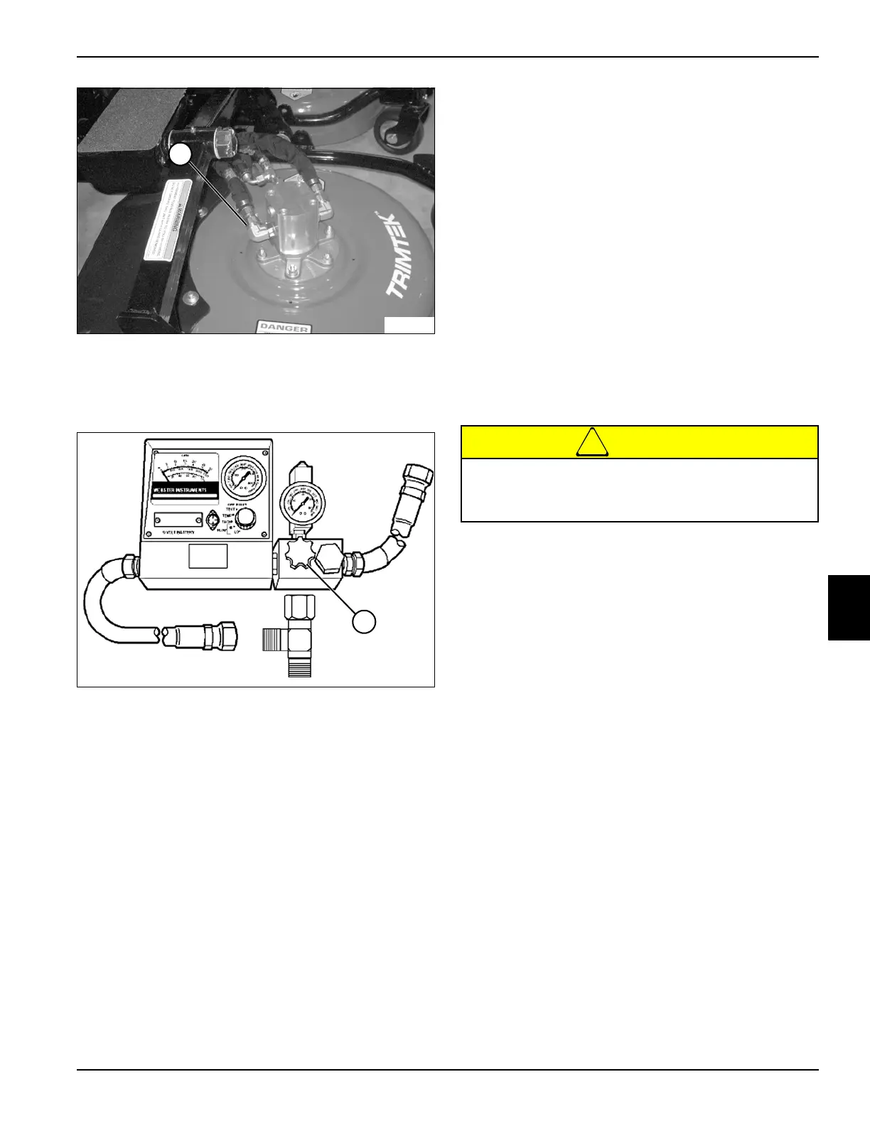
Figure 6-19
3. Install blocking disk at fitting (1) on right front cutting
unit motor, blocking oil flow from entering right front
cutting unit motor.
Figure 6-20
4. Open flow meter valve (2) completely.
5. Bypass seat switch.
Verify engine rpm is within specification (2850 rpm ± 50)
to ensure accurate hydraulic test results.
6. Start engine and run at full throttle (2850 rpm ± 50).
7. Use the flow meter to warm the hydraulic oil. Turn the
flow meter valve (2) until a reading of 1300 psi (90
bar) or one half of the relief valve rating is reached.
Warm oil to 120—150°F (49—65°C); open valve fully
after operating temperature is reached.
8. Disconnect park brake switch.
9. Engage cutting unit switch.
10. Slowly close flow meter valve (2) until pressure
reaches 1950 psi (134 bar). Read and record the
front cutting units pump loaded flow.
11. Calculate front cutting units circuit valve leakage.
(Step 8 of previous test – Step 10 / Step 8 of
previous test x 100 = Leak Percentage)
Is front cutting units circuit valve leakage 10% or
less?
YES The front cutting units circuit valve is good.
Proceed to step 12.
NO Proceed to next question.
Is front cutting units circuit valve leakage 11% to
20%?
YES The front cutting units circuit valve is
marginal. Additional testing is required.
NO Proceed to next question.
Is front cutting units circuit valve leakage 21% or
more?
YES Repair or replace deck valve. (See “Deck
Valve” on page 6-45.)
!
CAUTION
12. Continue to close flow meter valve (2) until zero flow
is obtained. Record cutting unit system relief valve
pressure.
13. Open flow meter valve (2) and stop engine.
Is cutting unit system relief valve pressure 2600
psi (179 bar)?
YES Cutting unit system relief valve is good.
Proceed to step 14.
NO Adjust cutting unit system relief pressure.
(See “Adjust Cutting Unit System Relief
Valve Pressure” on page 6-28.)
14. Disconnect and remove test equipment. Install all
hoses and fittings as noted prior to removal.
15. Install and connect all components as noted prior to
test.
16. Check hydraulic oil level. Add oil as needed. (Refer to
“Safety, Operation, and Maintenance Manual” for
correct oil specifications.)
TN1412
1
TN1363
2
Do not exceed 2650 psi (183 bar) when testing
system relief valve or equipment damage may
occur.
 Loading...


