6-40 4181383 First Edition
HYDRAULICS
6
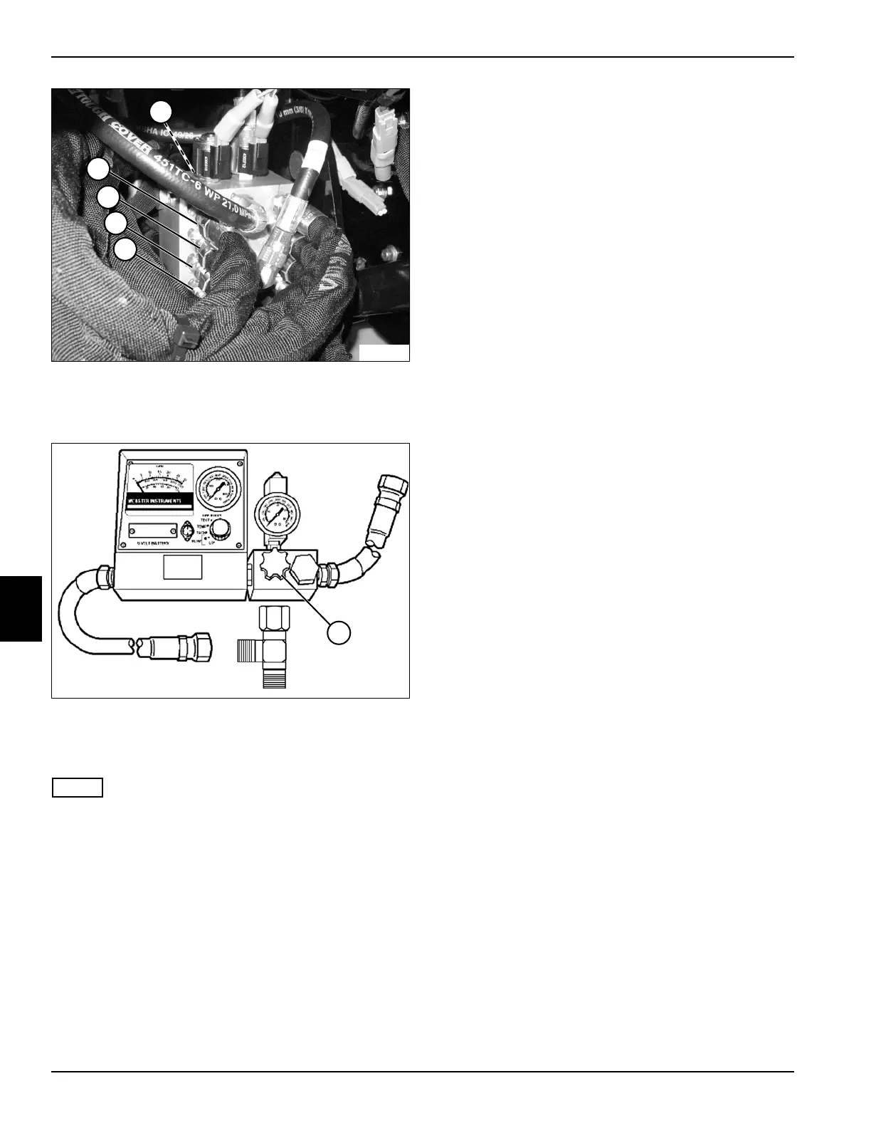
Figure 6-34
3. Install blocking disks at fittings (1—5) on lift valve,
preventing oil flow from entering lift cylinders.
Figure 6-35
4. Open flow meter valve (6) completely.
5. Bypass seat switch.
NOTE
Verify engine rpm is within specification (2850 rpm ± 50)
to ensure accurate hydraulic test results.
6. Start engine and run at full throttle (2850 rpm ± 50).
7. Use the flow meter to warm the hydraulic oil. Turn the
flow meter valve (6) until a reading of 900 psi (62 bar)
or one half of the relief valve rating is reached. Warm
oil to 120—150°F (49—65°C); open valve fully after
operating temperature is reached.
8. Hold the lever in the raise position.
9. Slowly close flow meter valve (6) until pressure
reaches 1300 psi (90 bar). Read and record the
lift/steer pump loaded flow.
10. Open flow meter valve (6) and stop engine.
11. Calculate lift valve leakage.
(Step 8 of previous test – Step 9 / Step 8 of previous
test x 100 = Leak Percentage)
Is lift valve leakage 10% or less?
YES The lift valve is good. Proceed to step 12.
NO Proceed to next question.
Is lift valve leakage 11% to 20%?
YES The lift valve is marginal. Repair or replace
as needed.
NO Proceed to next question.
Is lift valve leakage 21% or more?
YES Repair or replace lift valve. (See “Lift Valve”
on page 6-44.)
12. Disconnect and remove test equipment. Install all
hoses and fittings as noted prior to removal.
13. Install and connect all components as noted prior to
test.
14. Check hydraulic oil level. Add oil as needed. (Refer to
“Safety, Operation, and Maintenance Manual” for
correct oil specifications.)
TN1419
2
4
5
1
3
TN1363
6
 Loading...


