List of Figures
x Micro-Tech 9101/9201 Reference Manual, Rev J Thermo Fisher Scientific
List of Figures
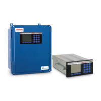
Figure 1–1. Field-Mounted Version of the Micro-Tech .............. 1-2
Figure 1–2. Panel-Mounted Version of the Micro-Tech ............ 1-3
Figure 1–3. A Typical 9101 Field-Mounted Installation ............. 1-8
Figure 1–4. Connectors on Underside of Enclosure ................. 1-9
Figure 2–1. Pivot-to-Load-Cell Distance ................................... 2-6
Figure 2–2. Number of Weight Idlers ........................................ 2-6
Figure 2–3. Pivot-to-First-Idler Distance ................................... 2-7
Figure 2–4. Pivot-to-Test-Weight Height ................................... 2-7
Figure 2–5. Pivot-to-Test-Weight Length .................................. 2-8
Figure 2–6. Pivot-to-Carriage Height ........................................ 2-8
Figure 2–7. Roller-to-Stringer Height ........................................ 2-8
Figure 2–8. Idler Spacing .......................................................... 2-9
Figure 2–9. Conveyor Angle ..................................................... 2-9
Figure 2–10. Location of Load-Cell Data ................................ 2-10
Figure 2–11. Belt-Scale-Code Entry Screen ........................... 2-28
Figure 3–1. Main Features of the Micro-Tech Console ............. 3-1
Figure 3–2. Run Screen ............................................................ 3-3
Figure 4–1. Four-Wire Load-Cell, No Sense Leads .................. 4-5
Figure 4–2. Four-Wire Load-Cell, with Sense Leads ................ 4-6
Figure 4–3. Six Wire Load-Cell, with Sense Leads ................... 4-7
Figure 4–4. Analog Troubleshooting—Confirm Voltage ........... 4-9
Figure 4–5. Analog Troubleshooting—Confirm Output ............. 4-9
Figure 4–6. Analog Troubleshooting—Confirm Loop .............. 4-10
Figure 4–7. Analog Troubleshooting—Verify Input ................. 4-11
Figure 4–8. Analog Troubleshooting—Verify Source Output .. 4-11
Figure 4–9. Analog Troubleshooting—Verify mA Loop ........... 4-11
Figure 4–10. Opto22 Troubleshooting—Output Module ......... 4-14
Figure 4–11. Opto22 Troubleshooting—Input Module ............ 4-15
Figure 4–12. DIO Troubleshooting—Inputs 6–13 ................... 4-16
Figure 4–13. DIO Troubleshooting—Sourcing ........................ 4-17
Figure 4–14. DIO Troubleshooting—Sinking .......................... 4-17