Chapter 3 ’Web Browser Interface’ — Advanced Settings
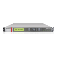
Amethyst III DTV Smart Switch 111
User Manual
When Switch is selected, a Switch input area is displayed so that you
can select the input to be switched on output from the Selected Input
drop-down list.
Figure 3-63. Switch input area is visible when switch operation is selected
4.
Repeat steps
2
and
3
for each relay you want to configure.
Example
For example, on an ASI Amethyst III, the relays configuration could be as
follows:
Relay #1: Switch #1 Input #1
Relay #2: Switch #2 Input #3
Relay #3: Switch #3 Input #5
Relay #4: Switch #4 Input #7