13-4 Communications Protocols
MODBUS RTU
Trio Motion Technology
Example
The following shows a typical set-up for a HMI panel running a Modbus Link. All
references below are to the programming software supplied by the HMI manufac-
turer and are not specific to any individual programming environment. See your
HMI programming instructions for the actual set-up sequence.
In the Controller Driver section choose “Modicon Modbus”, choose any Modicon
PLC type from the PLC setup section.
Program the panel to display a variable and open up a dialog box to Define
The Motion Coordinator is the slave so it will always wait for the HMI to request
the data required. With the set-up shown above, the display should poll the
Motion Coordinator for the value of VR(12) and display the data as a 4 digit
number.
Modbus Technical Reference
This section lists the Motion Coordinator’s response to each supported Modbus
Function.
Modbus Code Table
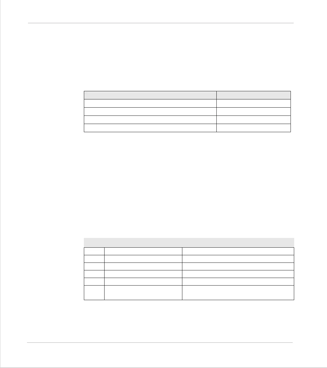
The following Modbus Function Codes are implemented:
Choose Example
Input bits, Output bits, Holding Register. Holding Register
Data size/type WORD (Binary)
Address Offset.
Display format and field width to be displayed. Numeric 4 digits
Code Function Name Action
1 Read Coil Status Returns input/output bit pattern
2 Read Input Status Returns input/output bit pattern
3 Read Holding Registers Returns data from VR() variables
5 Force Single Coil Sets single output ON/OFF
6 Preset Single Register Sets the value of a single VR() variable
16 Preset Multiple Registers Sets the values of a group of VR() varia-
bles