Motion Coordinator Technical Reference Manual
Communications Protocols 13-25
DeviceNet
DeviceNet Status LEDs
To see the DeviceNet status on the Motion Coordinator’s LEDs, you must set the
DISPLAY system parameter to 8. (See the DISPLAY system variable in chapter 8)
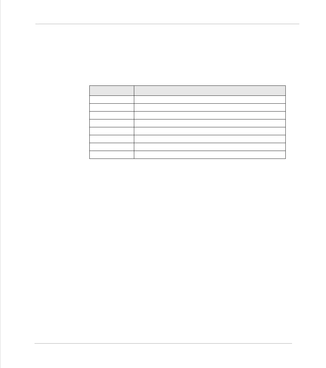
The Motion Coordinator’s I/O status LEDs are now read from 0 to 7 as follows:
LEDs 0 to 3 have the standard meanings as stated in the ODVA DeviceNet manual.
Module Status:
Off - No Power
Flashing Green/Red - Module self test
Flashing Green - Standby
Steady Green - Operational
Flashing Red - Minor Fault (software recoverable)
Steady Red - Major Fault
Network Status:
Off - Not On-line
Flashing Green - On-line, not connected
Steady Green - On-line, connected
Flashing Red - Connection timeout
Steady Red - Critical link failure
LED Function
0 - Amber Module Status - DeviceNet GREEN LED
1 - Amber Module Status - DeviceNet RED LED
2 - Amber Network Status - DeviceNet GREEN LED
3 - Amber Network Status - DeviceNet RED LED
4 - Amber Bus Off Count - bit 0
5 - Amber Bus Off Count - bit 1
6 - Amber Bus Off Count - bit 2
7 - Amber Bus Off Count - bit 3