2-4 Hardware Overview
Motion Coordinator MC202
Trio Motion Technology
Connections to the MC202
Wiring
All wires and cables should be of suitable size and type for the signals carried and
the operating environment.
Suitable wires would include multi-core screened cable for encoder feedback and
the serial links. The analog output from the MC202 (if used) should be connected
to the servo drive via a screened twisted pair. Drive enable outputs and 24v
inputs do not have a large current requirement so the choice of wire is not criti-
cal.
Connectors
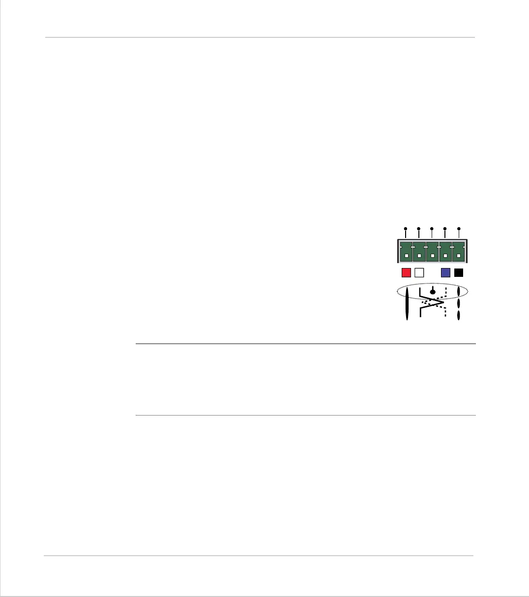
Top 5-Way Connector
This is a 5 way 3.81mm pitch connector. The connector is
used both to provide the 24 volt power to the MC202 and
provide connections for I/O expansion via Trio's P315 and
P325 CAN I/O expanders. 24 volts must be provided as this
powers the unit.
This 24 volt input is internally isolated from the I/O 24 volts
and the +/-10v voltage output. The MC202 has internal
power supply filters for the 24v power supply. This supply
should be isolated and independent from the I/O 24v.
Note:
The CAN connections are optional, although the CAN Screen must be
connected to Earth in all cases.
The V+(24v) and V- MUST be connected as this powers the MC202.
Power supply: 24V dc, Class 2 transformer or power source.
V+
SHIELD
CAN
-
L
CAN
-
H
V-