4-14 Daughter Boards
Servo Resolver Daughter Board
Trio Motion Technology
Servo Resolver Daughter Board
Trio Product Code P210
Description:
ATYPE
parameter for Servo Resolver Daughter Board = 5
The resolver daughter board provides the interface to a DC or Brushless servo
motor fitted with a resolver. The resolver port provides absolute position feed-
back within one motor turn. The resolver inputs are opto-isolated to maximise
the noise immunity of the system. The resolver port also provides an oscillator
output capable of driving many resolvers.
The resolver daughter board provides a hardware position capture function for
both the zero marker input and a dedicated 24volt registration input. Transi-
tions of either polarity on both these inputs can be used to record the position
of the axis at the time of the event within less than 1 micro seconds. This
practically eliminates time delays and avoids interrupting the processor fre-
quently in multi-axis systems.
The resolver daughter board provides a12 bit +/-10v voltage output to drive
most servo-amplifiers. The voltage output is opto-isolated as standard to max-
imise the noise immunity of the system.
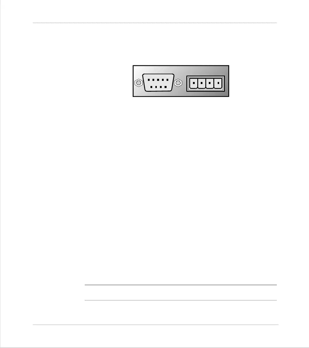
Connections:
Voltage Output
The +/-10v output voltage to drive external servo amplifiers is generated
between the V+ and V- pins. The voltage output is isolated and floating but if
multiple servo daughter boards are fitted it should be noted that the boards
share a common power supply for generation of the +/-10v. This means that
the V- pins should not be referenced to different external voltages.
Note:
The daughter board hardware inverts the voltage relative to the DAC
parameter.
RESOLVER
V+ V- R
0v
5 4 3 2 1
9 8 7 6