Motion Coordinator Technical Reference Manual
Communications Protocols 13-5
MODBUS RTU
(1 and 2) Read Coil Status / Read Input Status
(3) Read Holding Registers
(5) Force Single Coil
(6) Preset Single Register
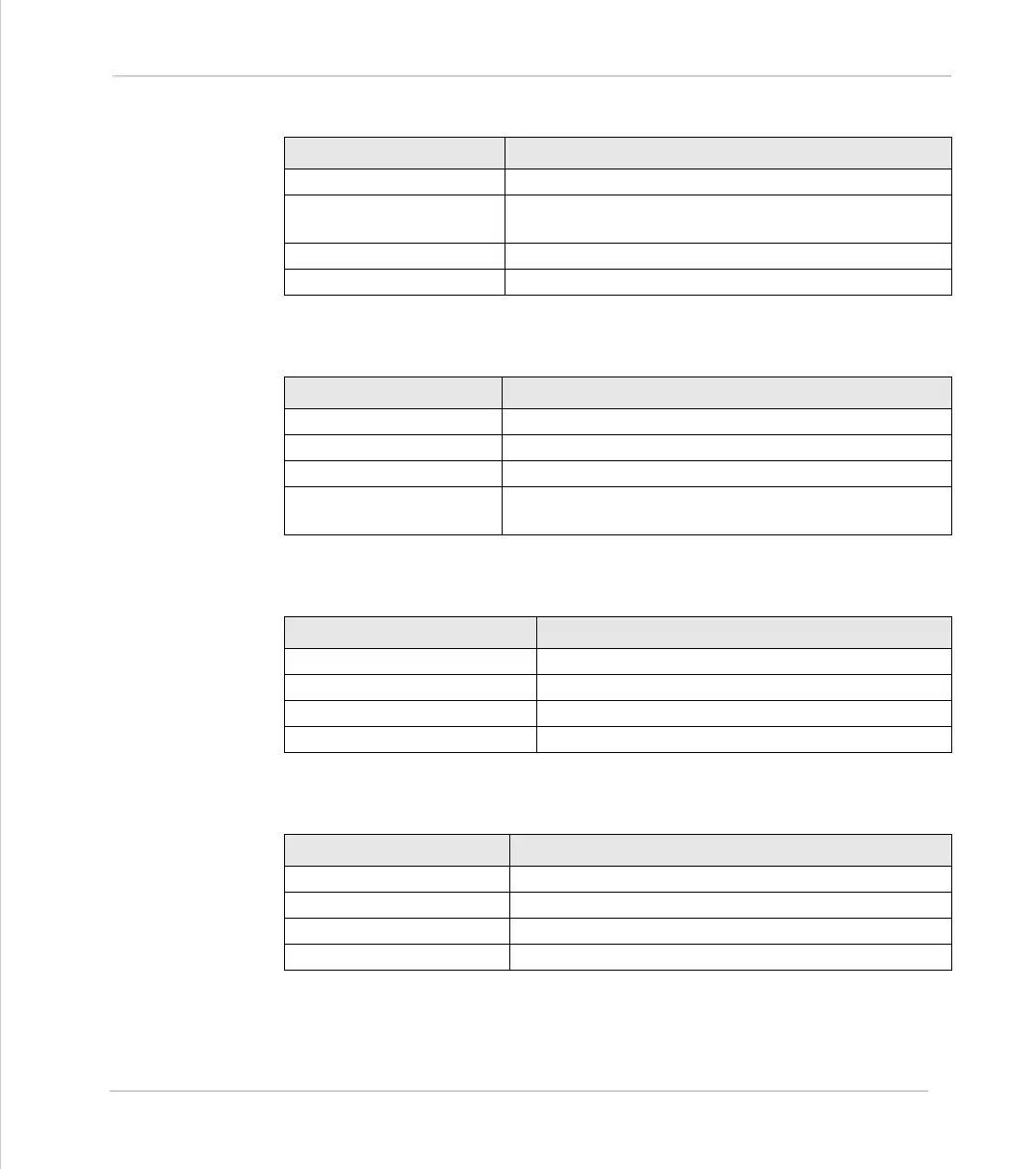
Modbus Function Code 1 & 2
Mapped Trio Function Read input word: IN(nn,mm)
Starting Address Range 0 to NIO-1 (NIO = Number of Input/Output Bits on
Controller)
Number of Points Range 1 to (NIO-1) – Starting Address
Returned Data Bytes containing “Number of Points” bits of data
Modbus Function Code 3
Mapped Trio Function Read VR() Global Variable
Starting Address Range 0 to 250
Number of Points Range 1 to 127 (Number of VR() variables to be read)
Returned Data 2 to 254 bytes containing up to 127 16-bit Signed Inte-
gers.
Modbus Function Code 5
Mapped Trio Function Set Single Output: OP(n,ON/OFF)
Starting Address Range 8 to NIO-1
Data 00 = Output OFF, ffH = Output ON
Returned Data None
Modbus Function Code 6
Mapped Trio Function Set VR() Global Variable: VR(addr)=data
Register Address Range 0 to 250
Data -32768 to 32767 (16 bit signed)
Returned Data None