Specifications
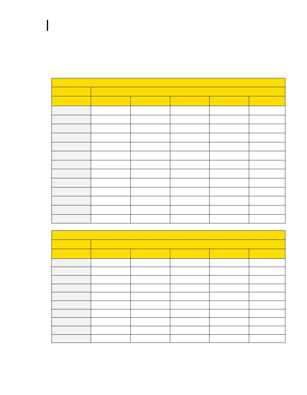
Estimated Logged Run Times
EVM Series User Manual
Estimated Logged Run Times
Standard EVM-7 (Memory and logged time)
(Logging the following Sensors: Dust, Temp, Humidity, CO
2
, Toxic, PID, Dew Pt)
Number of Measurements Logged
Number of Measurements Logged