Calibrate Sensors
Placement and Calibration of Sensors
EVM Series User Manual
Calibrate Sensors
Placement and Calibration of Sensors
Before you begin your measurement sampling, it is recommended to calibrate the sensors you will be
using. This chapter focuses on inserting and removing sensors, calibrating each sensor, viewing past
calibrations, and how to verify your calibration set points. (Reference the following sections which apply
to your installed sensor components.)
Calibrating sensors include:
Particulate sensor
Pump flow rate calibration
CO
2
and O
2
sensor
Toxic sensors
Photo-Ionization Detector (PID) sensor (for VOCs)
Temperature (temp) and Relative humidity (RH) sensors
Inserting and Removing Sensors
1. The sensors you purchased with your EVM will be inserted, factory calibrated, and ready for usage.
To understand how to insert or replace a sensor this is discussed in the procedures below.
NOTE: To order new sensors when expired, see Appendix A, Replacement and optional parts.)
Inserting sensors
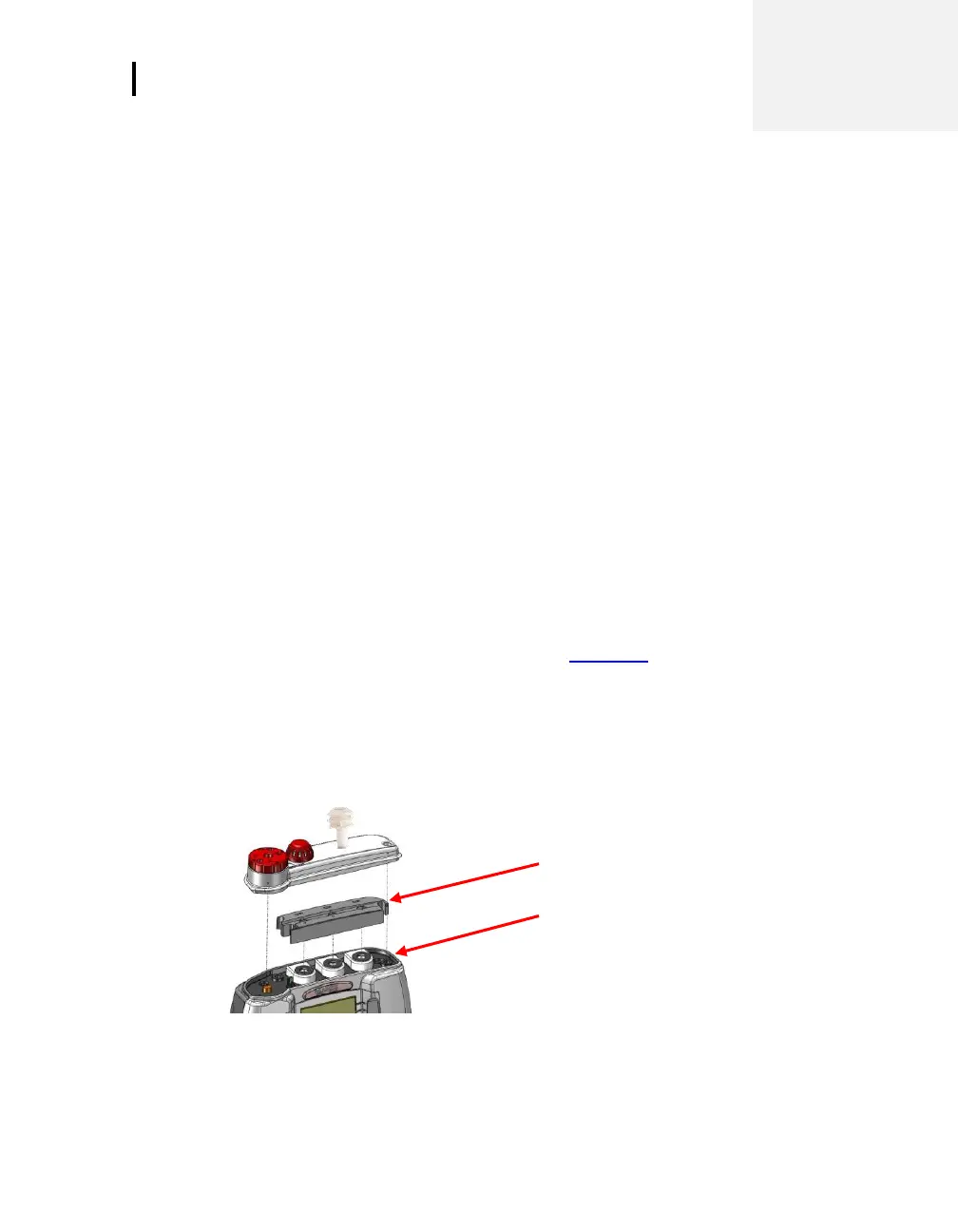
2. Ensure the instrument is turned off and the external power cord is disconnected. Next, remove the
sensor bar by unscrewing two screws from the top compartment with a screw driver.
3. Lift the cover off and set aside. (The location of the sensors is indicated in Figure 4-2.)
4. Remove the black manifold casing.
Figure 4-1: Sensor housing and manifold