Gas Sensors Sampling
Gas Sensors and Path
EVM Series User Manual
Gas Sensors and Path
TSI’s unique smart sensor technology includes automatic sensor recognition, calibration levels,
temperature compensation information and other valuable data that travels with the sensor from one
unit to another.
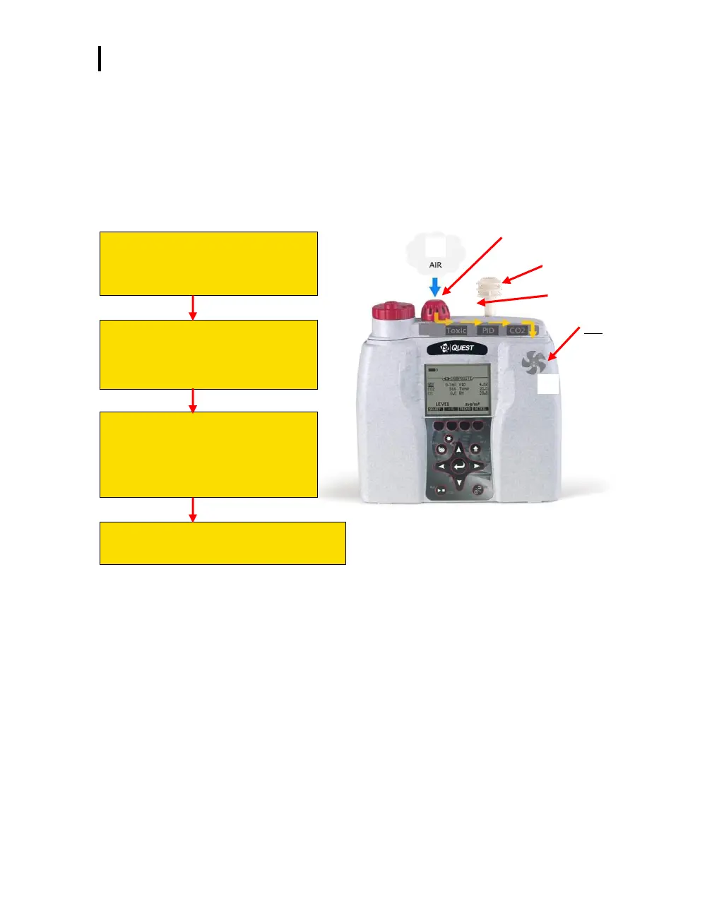
The following diagram illustrates the gas sensor path for Toxic, CO
2
, and PID sensors. It also identifies
the temperature sensor for additional analysis/measurements.
Figure 1-3: Gas sensor path illustration
(1) AIR INLET COVER
The path begins with the air pulling
through the air inlet cover.
(2) GAS SENSOR CHAMBERS
The air continues through the gas
sensor bar passing the Toxic, PID, and
CO
2
sensor chambers.
(3) Fan
It is continuously ventilated by the fan.
(NOTE: When the pump is off, the fan
can be heard near the louvers on the
back cover.)
(4) Temperature sensor
Measures the ambient air temperature.