Product description
Functions and operation modes
Hans Turck GmbH & Co. KG | T +49 208 4952-0 | more@turck.com | www.turck.com
07.00 | 2022/09 | 14
HF extended mode
All functions of the HF compact mode are included in HF extended mode. It is also possible
with fragmentation to transfer more than the set data size per write or read cycle (example: 128
bytes). The operation mode is suitable for single-tag and multitag applications.
NOTE
Not all commands are supported in multitag mode.
The user can set a command timeout to define the time for the execution of a command.
HF extended mode enables the use of Continuous Mode for the repeated execution of an In-
ventory, tag info, read or write command. In Continuous Mode the read/write head executes
the commands autonomously. Different data is stored in the internal memory of the interface.
The memory operates as a FIFO memory.
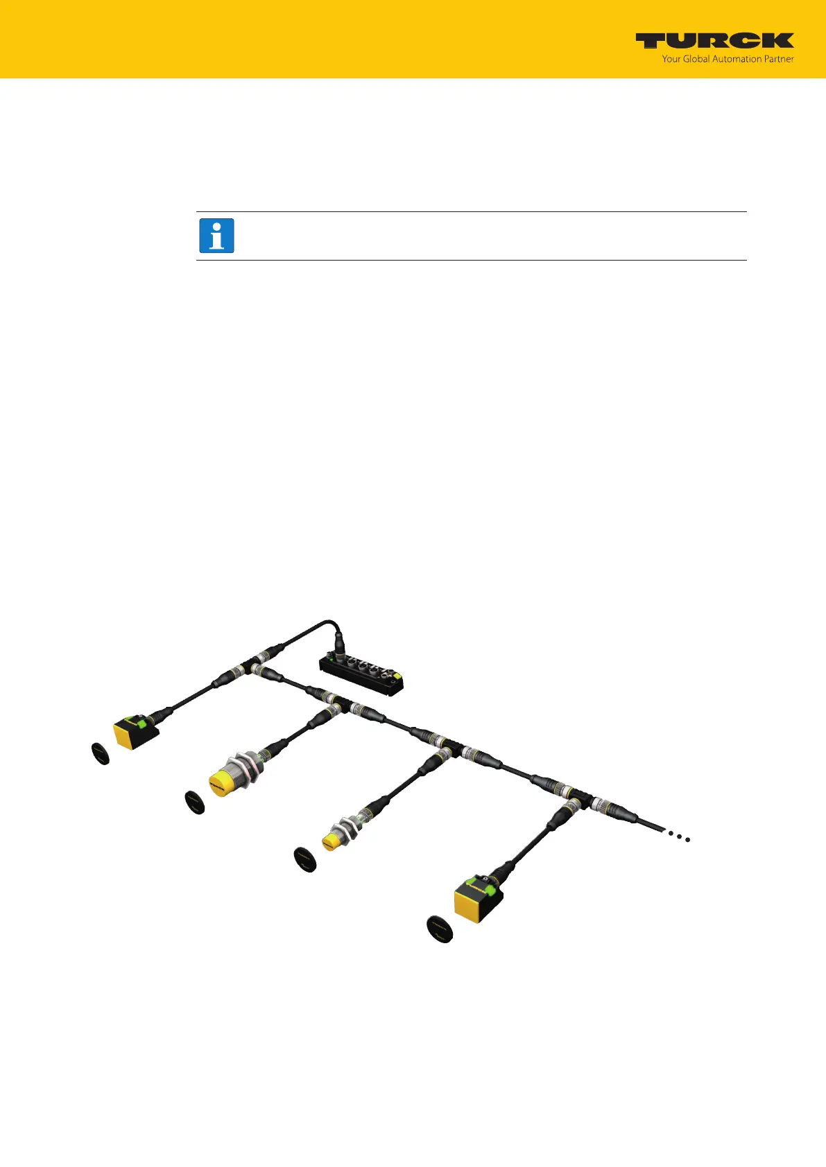
HF bus mode
In HF bus mode up to 32 bus-capable read/write heads per RFID channel can be connected to
the RFID module. An additional power supply may be required depending on the number and
power consumption of connected read/write heads. A power consumption analysis of the con-
nected read/write heads is required in order to determine the additional power supply re-
quired. A tool is provided at www.turck.com/hf-busmodus for calculating the power.
Every connected read/write head supplies a “ Tag present” signal in HF bus mode. HF bus
mode is suitable for static applications and very slow dynamic applications because a com-
mand can only be processed by one read/write head at a time.
In HF Continuous bus mode a command is performed simultaneously at all read/write heads in
a bus topology. The logged data is stored in the ring memory of the module.
TBEN-S2-2RFID-4DXP
VT2-FKM5-FKM5-FSM5
RFID connection cable
(e.g. RK4.5T-0.3-RS4.5T/S2503)
TN-M18-H1147/C53
TN-CK40-H1147/C53
TN-M30-H1147/C53
up to 32 per port
Fig.2: HF bus mode setup
 Loading...