572
Model
No Page
FIELDMASTER, fitting instruction
412.08.1998 6000---8750 39.18 (10)
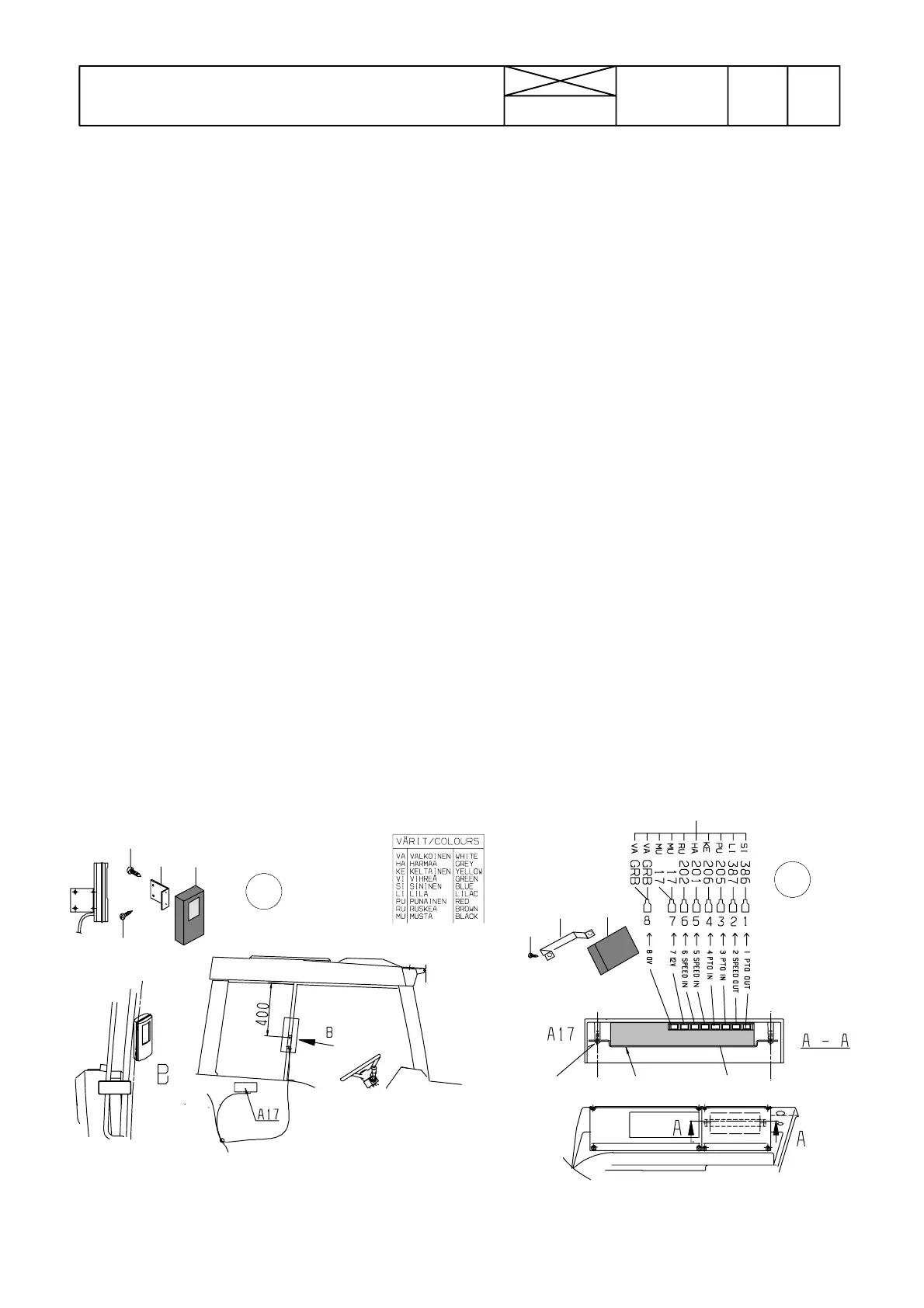
--- Tractors without earlier sensors (B7 ja B6):
Slacken the lead---in hole cover in the bottom of
the lever console and pass the sensor connec-
tors into the cab.
Connectthesensorwireloom 9 connector
“X1E” with the corr. connector of the wire loom.
Wire loom connectors “X34” and “X39” are not
connected.
--- Tractors with ACD power lift (without PTO sensor
B7):
Connectthewireloom9 connector “X34 * ” with
the connector “X34” in the lever console. Other
connectors are not connected.
--- Fasten the earth wire with the cable shoe under
eart point GR4 in the bottom of the lever console
(tyresidepoint).
--- If the tractor has a radar, the radar wires are con-
nectedtothefreehalfofconnectorX48,seepic-
ture D:
--- wire 1 (white) to pin 1
--- wire 305 (lilac) to pin 2
--- wire 15 (brown) to pin 3
--- In addition, wire loom 8 wire no. 305 (lilac)
must be connected to the pin 5 of connector
“X1E”
--- Connect connector “X7C” to the corr. connector
in the lever console.
--- W i r e lo o m 8 connectors X1L and X45 are not
connected.
Connector X47 is intended to use for the optio-
nal GPS system (LH---AGRO).
23
4
5
1
10
11
1011
1
A
B