577
Model
No Page
FIELDMASTER, fitting instruction
912.08.1998 6000---8750 39.18 (10)
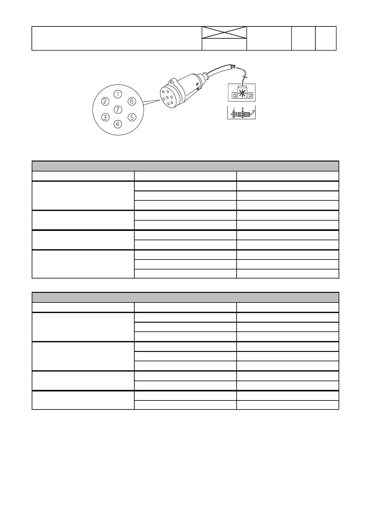
Poles have been numbered on the plug casing. The
tables below show how the implement sensors are con-
nected to the plug.
Sprayer
Sensor Wire color Plug pin
blue 5
Flow meter
brown 2
black 6
Wheel sensor blue 4
brown 5
Implement sensor blue 7
brown 5
Pressure sensor blue 6
brown 5
black 1
Fertilizer distributor
Sensor Wire color Plug pin
RPM sensor 1 blue 6
brown 5
black 1
RPM sensor 2 or weight module blue 6
brown 5
black 2
Wheel sensor blue 4
brown 5
Implement sensor blue 7
brown 5