6-10 The GC Interface
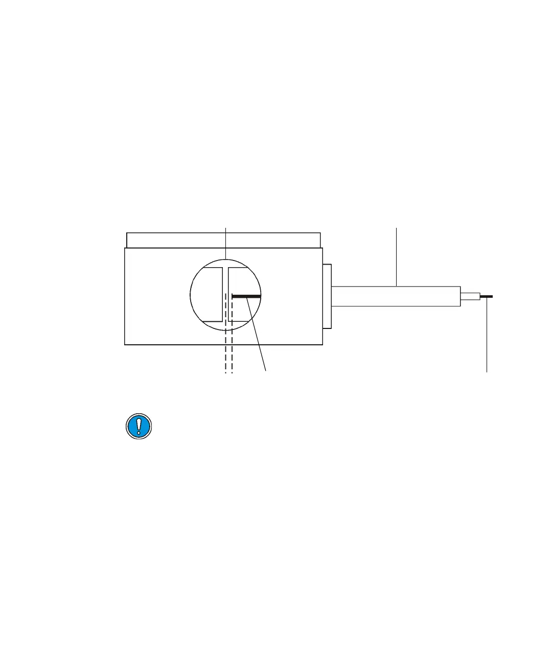
6. Insert the GC column through the GC interface transfer line until the
end of the column is approximately 5 mm from the center line of the
source.
Tip: To determine the correct position, look into the inner source probe
port from the front with the inner source removed. The end of the GC
column will be visible as it enters the source housing, as shown in the
following figure.
Tip: For CI operation, the column can be positioned closer to the center
line of the source.
Positioning the end of the GC column:
7. Use correction fluid or a permanent marker to mark the position of the
column relative to the 1/16-inch retaining nut.
8. Retract the GC column by 50 mm into the transfer line or pull back the
interface until it reaches the stopper.
Caution:
• To avoid compromising sample data, ensure that no correction
fluid enters the vacuum side of the instrument (see step 7).
• To avoid damaging the GC column and inner source chamber
assembly, the GC column must be retracted so that its end is
within the outer source housing before fitting the inner source
(see step 8).
GC column
5mm
GC transfer lin