Chapter 6 Installation and connection 40058725 BTA Alpha HSM
Version: 12.19.17 Page 40 of 112 GB
*2
Connection an compressed air
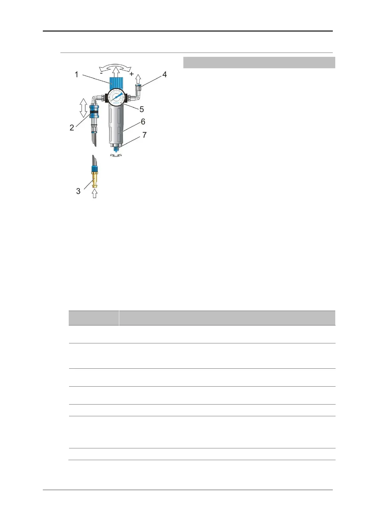
Fig. 6-4: Maintenance unit
CONNECTION FITTING (TO THE LABELER)
COMPRESSED AIR PRESSURE GAUGE
*² only with an appropriately equipped labeler.
Prerequisites
The compressed air supply (KS4-CK-6 connector) is located in the vicinity of the
utilization site (max 1.5 metres away) according to Technical Specifications.
Compressed air connection line with KS4-CK-6 coupling connector, pneumatic
hose and accessories for pneumatic components are installed.
Instruction
How to connect the labeling machine with compressed air.
If available, make sure that the slide plate valve is in the OFF position (slide
plate down, comp. Fig. 6-4 = ON position!).
Connect the labeler to the maintenance unit via the connector (4) with the
help of the supplied pneumatic hose. Check the connection for a tight fit (the
hose can not be pulled off).
Connect the coupling plug (Pos 3, Fig. 6-4) of the compressed air
connection cable with the coupling of the compressed air supply.
To switch on the compressed air, move the valve to the ON position. If
adjustments are necessary for the compressed air, refer to steps 5-7.
Pull the regulator knob (pos. 1, Fig. 6-4).
Set the compressed air to the desired value (5 bar is the default value). Turn
the knob counter clockwise (arrow direction "+") to increase the inlet
pressure.
Turn the knob clockwise (arrow direction "-") to reduce the inlet pressure.
To lock, press the regulator knob (pos. 1, Fig. 6-4).