Chapter 6 Installation and connection 40058725 BTA Alpha HSM
Version: 12.19.17 Page 48 of 112 GB
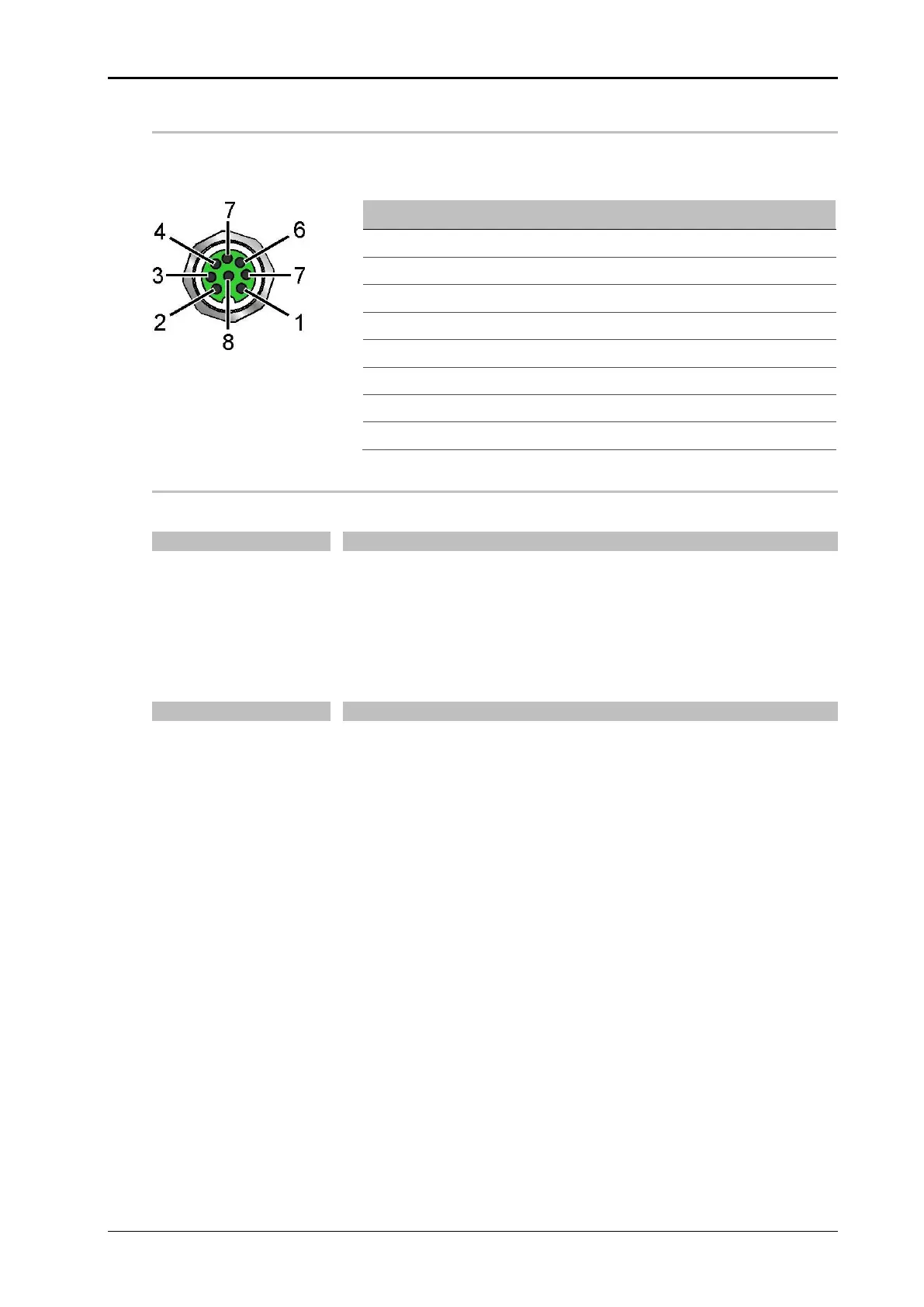
I/O signal interface (X9)
The I/O signal interface provides inputs and outputs to a higher-level controller (e.g. PLC).
The connection is established as a 8-pin M12 socket.
Fig. 6-13: Flange socket, 8-pin (pin
assignment: Exterior view)
OUTPUT SIGNAL: LOW LABEL WARNING
Signal description
Input signals:
The system-internal 24 V power supply is available at Pin 7 and
8.
Labeler goes into readiness for labelling (in the "RUN" or
“STANDBY” mode).
Output signals:
The signal is active when the labeler is ready for operation and
no error message is pending.
The signal is active as soon as the remaining label roll falls be-
low a given diameter (low label pre-warning sensor required).
The SYNC output is configurable via display and creates an im-
pulse after or during an application cycle.