Chapter 7 Settings and commissioning 40058725 BTA Alpha HSM
Version: 12.19.17 Page 55 of 112 GB
Open the clamping of the clamping bar (pos. 1, Fig. 7-6) and pull it off.
Place the label roll on the adapter ring (pos. 2, Fig. 7-6).
Replace the clamping bar on the mounting axle (pos. 4, Fig. 7-6) and lock it
with the clamping.
Route the label liner around the deflection roller (pos. 5, Fig. 7-6).
Guide the label web around the dancer arm according to the threading dia-
gram (pos. 3, Fig. 7-6) and continue to the dispensing. Release the brake
liner of the unwinder device by pressing the dancer arm.
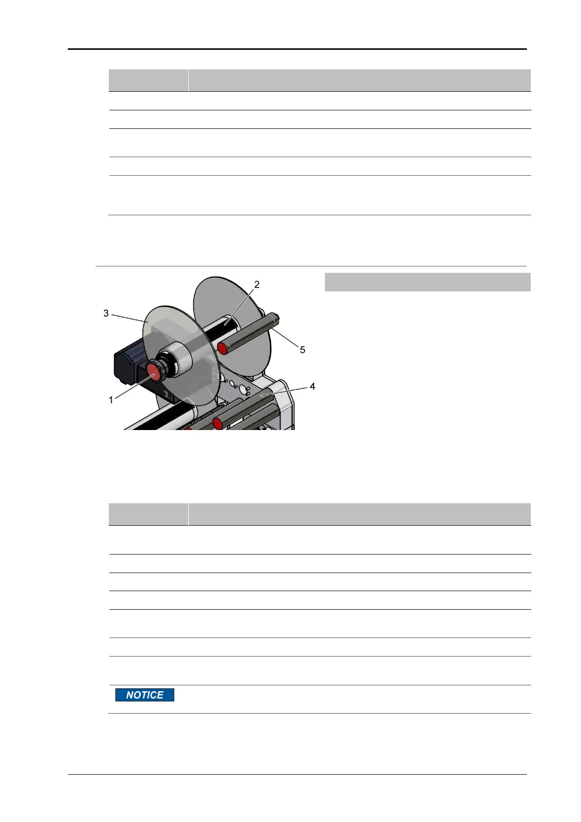
Unwinder (performance and motorized)
Fig. 7-7: Unwinder P, load labels
Turn the star grip (pos. 1, Fig. 7-7) counter clockwise, in order to open the
clamping of the mounting axle (pos. 2, Fig. 7-7).
Pull off the clamping disc (pos. 3, Fig. 7-7).
Place the label roll on the mounting axle as far as it will go.
Replace the clamping disc on the mounting axle.
Turn the star knob clockwise until the star knob engages and the label roll is
firmly seated on the mounting axle.
Route the label liner around the deflection roller (pos. 4, Fig. 7-7).
Guide the label web around the dancer arm according to the threading dia-
gram (pos. 5, Fig. 7-77-11) and continue to the dispensing.
In order to open the clamping, pull the star knob and turn it counterclockwise
until it clicks into place.