Chapter 7 Settings and commissioning 40058725 BTA Alpha HSM
Version: 12.19.17 Page 57 of 112 GB
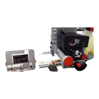
Drive
Fig. 7-10: Drive unit, insert labels
Press the lever (pos. 1, Fig. 7-10) downwards, so that the pressure roller
(pos. 2, Fig. 7-10) is free.
Guide the backing tape between the drive roller (pos. 3, Fig. 7-10) and the
pressure roller (pos. 1, Fig. 7-10) and also over the guiding (pos. 4, Fig.
7-10).
Swing the lever upwards until it clicks into place.
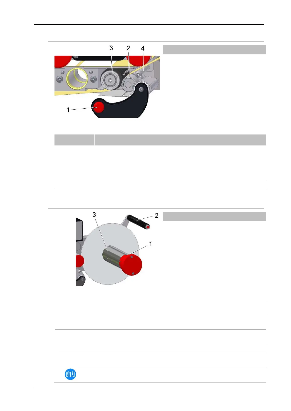
Rewinder (mechanical)
Fig. 7-11: Rewinder mechanical, loading labels
Pull out the clamp (pos. 1, Fig. 7-11) on the rewinder axle remove any exist-
ing carrier material roll.
Guide the carrier material over the dancer arm (pos. 2, Fig. 7-11) to the re-
winder axle.
Rewind the carrier material around the rewinder axle (pos. 3, Fig. 7-11) and
clamp it with the clamp.
Turn the rewinder axle until the carrier material is tightened.
Make sure that the label web runs in a straight line from unwinder to rewind-
er.
Set the web brake on the peeler plate to a low braking force.