430 Ink Jet Printer Service and Maintenance Manual
84
Issue 2
Part No. 306-0430-102
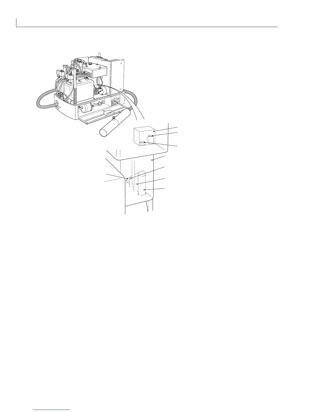
Fluid Management System (FMS)
(
1
)VMS
(
2
) VMS high level sensor
(
3
) VMS low level sensor
(
4
) Mixer tank
(
5
) Mixer tank level low sensor
(
6
) Mixer tank level OK sensor
(
7
) Mixer tank level high sensor
6
5
4
7
8
1
2
3
(
8
) Temperature sensor
Figure 34 FMS Components
The FMS (Figure 32 (
7
)) has solenoid valves V3 (
5
), V6 (
3
), V8 (
4
) and V7 (
6
) externally mounted on it. It
houses the following components:
•
Mixer tank (Figure 34 (
4
)).
•
Mixer tank level high sensor (
7
).
•
Mixer tank level OK sensor (
6
).
•
Mixer tank level low sensor (
5
).
•
Mixer tank ink temperature sensor (
8
).
•
Viscosity Monitoring System (VMS) (
1
).
Viscosity Monitoring System (VMS) Chamber (located inside the FMS top box)
The VMS chamber is small and incorporated as part of the FMS ink system top box moulding.
The top of the VMS chamber is covered by an injection moulded cover, which is secured with a gasket and four
screws.
The VMS top cover incorporates a pre formed stainless steel pipe, which is connected to V3 via a PTFE tube.
The pipe allows ink into the VMS chamber during the filling period.
The VMS chamber has two ink level detectors, ‘High’ and ‘Low’. These detectors can be of the optical or metal
rod conductivity type. The detector type is dependent upon the type of machine. The 430 machine uses the
optical type detector.