Disassembly and Assembly: Nozzle Assembly
Issue 2
137
Part No. 306-0430-102
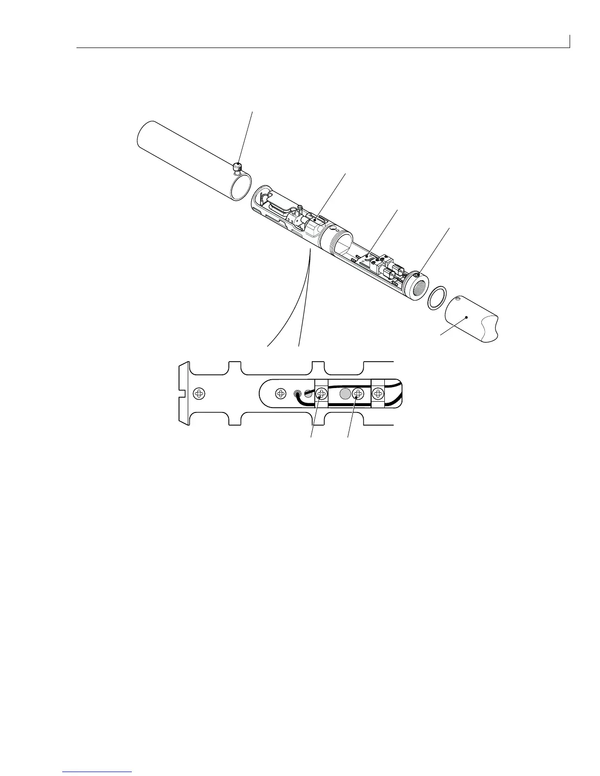
Nozzle Assembly
2
1
3
4
6
7
5
(
1
) Nozzle assembly (
5
) Heater manifold
(
2
) Knurled screw (
6
) Cable/nozzle clamp screw
(
3
) Rear cover securing screw (
7
) Nozzle adjusting screw
(
4
) Rear cover
Figure 68 Printhead Nozzle Removal and Replacement
Removal
1
Slacken the knurled screw Figure 68 (
2
) and slide the front cover off the printhead.
2
Remove and retain the two rear cover securing screws (
3
) and slide the rear cover (
4
) off the printhead.
3
Identify the leads from the nozzle to the wiring loom. Remove the heatshrink and desolder the connections.
4
Disconnect the ink feed and return tubes from the heater manifold (
5
).
5
Remove and retain the cable/nozzle clamp screw (
6
) and the nozzle adjusting screw (
7
).
6
Slide out the nozzle assembly (complete with last chance filter).
Note: Ensure that the new nozzle is the correct type prior to Installation: