Disassembly and Assembly: I/O Board
Issue 2
111
Part No. 306-0430-102
Installation
Note: The 430 uses an issue 3 I/O board identified by a blue PCB as opposed to a green PCB. This
board may be used on older 450/460/470 machines. Boards previous to issue 2, however, must
not be used on the 430.
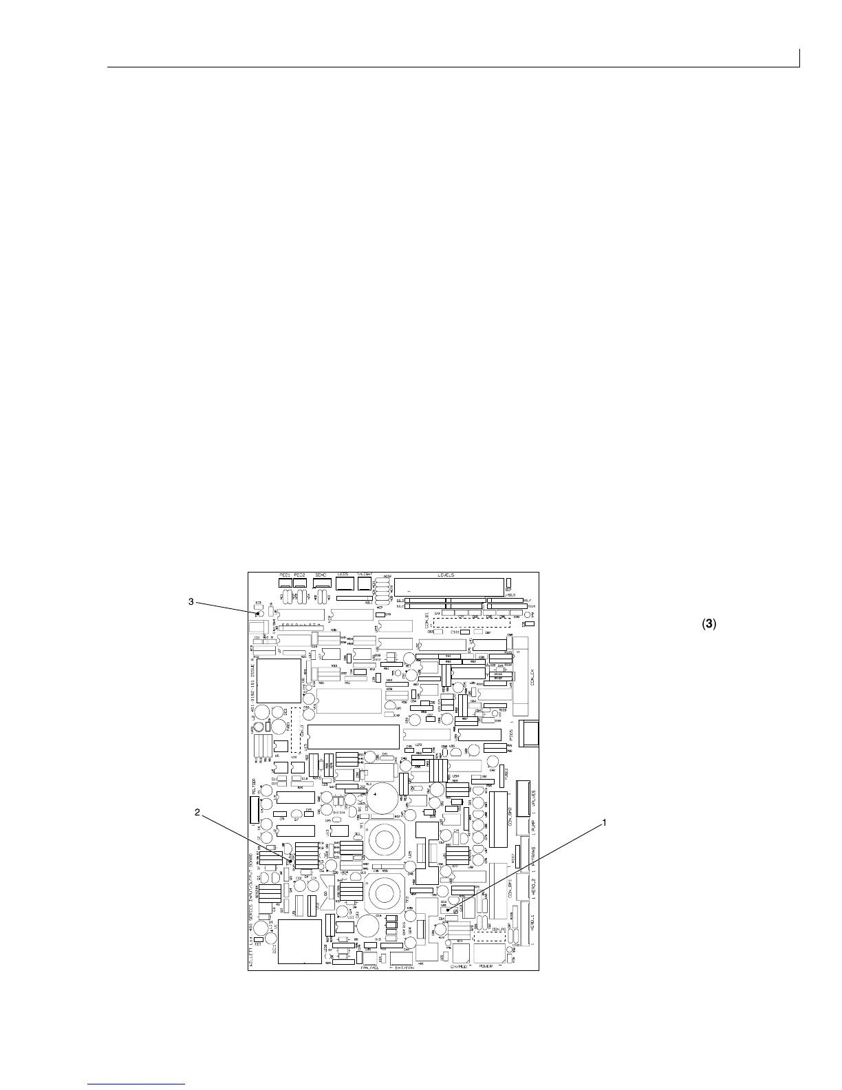
1
Position the I/O board (Figure 51 (
3
)) on the 18 mm stand-offs (
1
) with the component side facing out and
the LEVELS connector at the top right-hand corner.
2
Push the I/O board on to the CPU board (
2
), ensuring that the interboard connectors mate correctly.
3
Secure the I/O board using the six nuts and washers retained at
Removal
step
3
.
4
Reconnect the connectors.
5
Refit the ink pump motor driver board as noted at
Removal
step
1
.
Calibration
When a new Mk. 3 I/O board is fitted, you must calibrate the 285 V rail limit as described below:
1
Reconnect power to the printer and switch on the printer.
2
Set a digital voltmeter to a range suitable for measuring 285 V DC.
3
Connect the positive probe to TP2 (Figure 52 (
2
)) and the negative probe to TP1 (
3
).
4
Adjust VR1 (
1
) to give a reading of 285 V ±1 V.
5
When the adjustment is complete, seal VR1 with a suitable sealing compound.
6
Recalibrate the system (see
Restore Calibration Parameters
, page 40) and calibrate the modulation value
(see
Modulation Calibration (Manual)
, page 35).
(
1
)VR1
(
2
)TP2
2
3
1
(
3
)TP1
Figure 52 I/O Board Calibration