Technical Description: Electronics System
Issue 2
53
Part No. 306-0430-102
Connector Panel
3
21
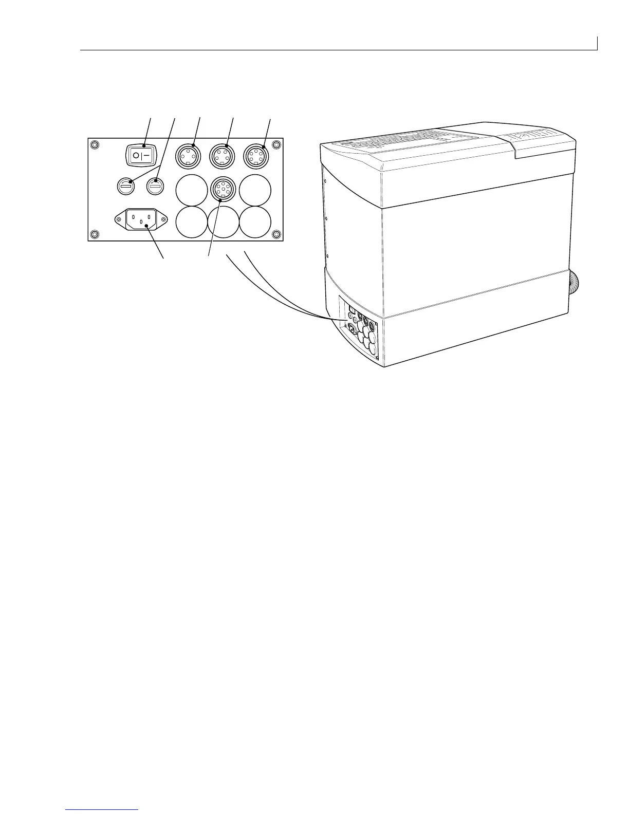
PRINT TRIGGER 1 SHAFT ENCODER COMM 1
4 5 6
STATUS O/P
7
(
1
) On/Off switch (
5
) Shaft encoder connector
(
2
) Fuse holders (
6
) COMM1 Connector
(
3
) Mains inlet connector (
7
) Status O/P connector (option)
(
4
) Print trigger 1 connector
Figure 21 Connector Panel
The connector panel is a stainless steel pre-drilled plate fitted to the printer base and secured by four screws.
The connector panel is fitted with the components listed below.
•
A mains inlet connector (
3
) with a single pole rocker switch (
1
) and fuseholders (
2
) for supply and return
lines.
•
A 3 way DIN connector (
4
) for print trigger 1.
•
A 4 way DIN connector (
5
) for a shaft encoder.
•
A 5 way DIN connector (
6
) for an RS232 serial communications link. RS232 can only be used over relatively
short distances (15 metres maximum).
•
A 6 way DIN connector (
7
) for a set of status traffic lights (optional).