430 Ink Jet Printer Service and Maintenance Manual
74
Issue 2
Part No. 306-0430-102
Ink Pump Motor Driver Board
J1
401 - 0193-101 ISS 1
VALVES
I/O VALVES
D2
R23 R24
V3
R26
R10
R19
R27
C13 C12
R48
R37
R35
R16
R3
R38
R6
R14
J2
R1
CON 1
CON 2
R43
R45
R4
R44
R39
R52
R54
R55
R49
R50
R33
V5
C15
C14
R51 D10 D8 R53 D11 D9
C8
R28 JP1 V1
C1
C7
C9
R29
JP2
R31
R12 R13
R32
R7
R25
R11
R17
R20
R30
C3 R8
R9
C4
V4
C5 R21 C6 R18
C2
R22
R15 R2
R5
D4
J6
J7
Q10
Q9
D3
INHIBIT
IS01
Q2
Q5Q1
R42
R46
J4
Q8
123
R40
D7
R47
Q4
C10
Q3
R34
Q6 V7
C11
R36
D6
V6
D5
Q7
R41
V2
+
+
+
+
+
D
GDS
D
GDS
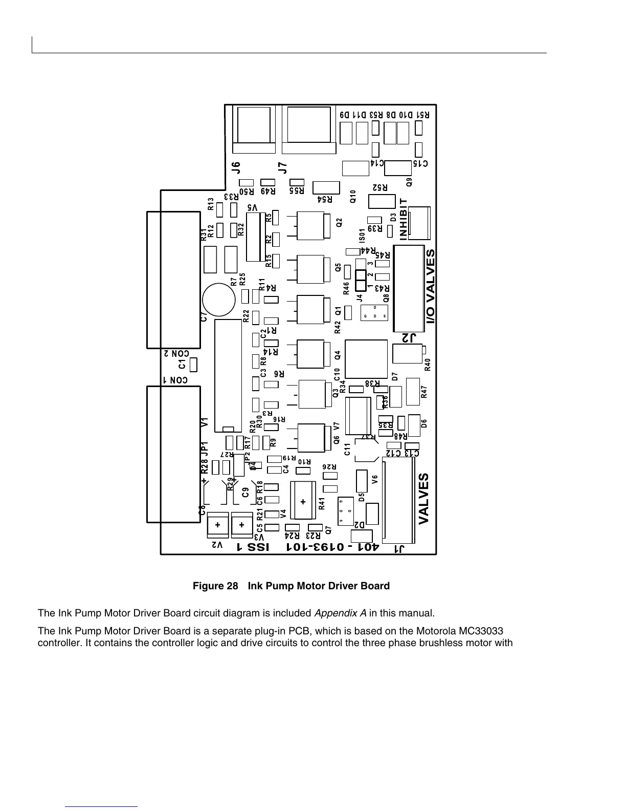
Figure 28 Ink Pump Motor Driver Board
The Ink Pump Motor Driver Board circuit diagram is included
Appendix A
in this manual.
The Ink Pump Motor Driver Board is a separate plug-in PCB, which is based on the Motorola MC33033
controller. It contains the controller logic and drive circuits to control the three phase brushless motor with Hall
effect position sensors, which are used to drive the pump.
The speed of the motor is determined by the Pulse Width Modulation (PWM) input from the I/O board and
feedback from the pressure transducer. The PWM level is buffered by U4A and the pressure signal is inverted
by U4B. These signals are combined in the error amplifier U4C with an offset generated by R24 and the -12 V
supply. U4C and U4D form an integrator with a time constant of 100 ms defined by C6 and R18. The output of
the integrator is coupled to the motor controller via diode D1 preventing the input to the controller becoming