System Calibration and Test: Introduction
Issue 2
25
Part No. 306-0430-102
S
YSTEM
C
ALIBRATION AND
T
EST
Introduction
The system calibration and test procedures described below should be performed as necessary to commission
the machine after repairs have been carried out. All or part of the procedure may be required, as indicated in the
failure diagnosis and repair instructions at the beginning of this section. The procedures may also be used as an
aid to fault finding.
Earth Continuity Test
WARNING - EARTH CONTINUITY
To ensure safe earthing the resistance between the mains lead earth wire and the test
points must be less than 1
Ω
.
1
Using the multimeter, test between the green/yellow earth wire in the mains lead and the following points.
2
The front and rear panels.
3
With the covers removed from the printer and the top moulding raised, check between the green/yellow wire
in the mains lead and the following points:
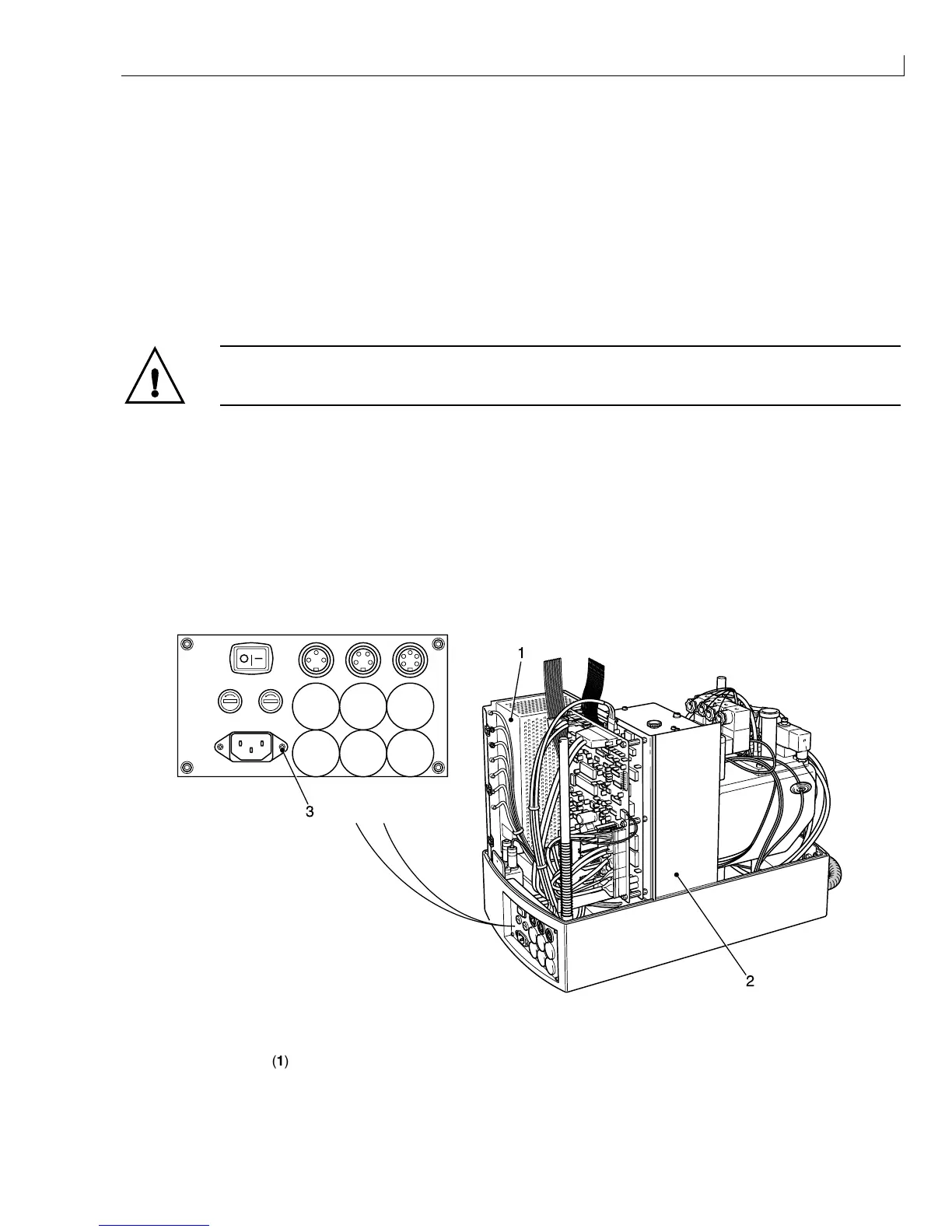
Mains supply filter screw (Figure 12 (
3
)).
PSU cover (
1
).
Baffle plate (
2
).
Earth point on printhead (located under the rear cover).
PRINT TRIGGER 1 SHAFT ENCODER COMM 1
PRINT TRIGGER 2 STATUS 0/P
3
1
2
(
1
) PSU cover (
2
) Baffle plate (
3
) Mains supply filter screw
Figure 12 Earth Continuity Test Points