430 Ink Jet Printer Service and Maintenance Manual
110
Issue 2
Part No. 306-0430-102
I/O Board
21
3
5
6
4
(
1
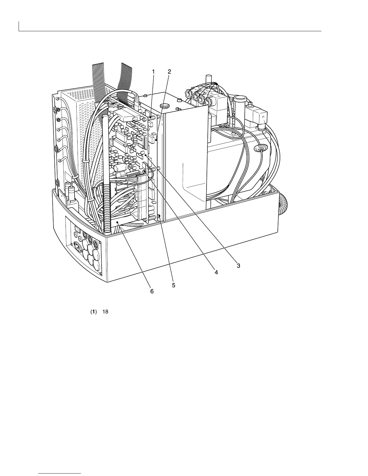
) 18 mm stand offs (
4
) Securing nuts and washers
(
2
) CPU (
5
) 10 mm stand offs
(
3
) I/O board (
6
) Ink pump motor driver board
Figure 51 I/O Board and CPU Board - Removal and Installation
Removal
1
Remove the ink pump motor driver board (Figure 51 (
6
)) from the I/O board. Note the orientation for
Installation.
2
Remove all connectors from the I/O board noting their position and orientation for Installation.
3
Remove and retain the six securing nuts and washers (
4
). Pull the I/O board away from the CPU board (
2
)
taking care not to damage the interboard connectors.