430 Ink Jet Printer Service and Maintenance Manual
128
Issue 2
Part No. 306-0430-102
Fan
Caution - Equipment Damage
Take care to ensure that the fan fail sensor is not damaged when removing or installing the filter
housing.
Removal
1
Disconnect the FAN/EHT plug from the I/O board.
2
Identify the two leads that go to the fan (pins 4 and 5) and remove them from the plug by pressing the crimp
release lugs on the side. Make a note of the colour and destination of each lead.
3
Remove and retain the two screws that secure the baffle plate to the base moulding.
4
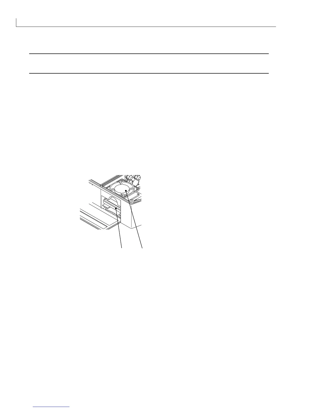
Move the baffle plate assembly to one side to reveal the fan (Figure 63 (
1
)).
5
Support the filter housing (
2
) and remove the four screws securing the fan. These screws fasten into holes
in the filter housing, which will drop if not supported.
6
Remove the filter housing and put to one side.
7
Remove the fan from the electronics compartment.
1
2
(
1
)Fan
(
2
) Filter housing
Figure 63 Fan Removal
Installation
1
Place the fan (
1
) in position in the electronics compartment. Hold the fan filter housing (
2
) in position in the
filter compartment and align the fixing holes with the holes in the fan casing. Secure the fan to the filter
housing using the screws retained at
Removal
step
5
.
2
Insert the crimped ends of the fan power lead into the FAN/EHT plug in the positions noted in
Removal
step
2
. It may be necessary to open the crimp release lugs to enable the crimp to lock back into position inside
the connector.
3
Put the baffle plate assembly back into its correct position and secure it to the base moulding using the
screws retained at
Removal
step
3
.
4
Connect the FAN/EHT plug to the I/O board.